3.3 KiB
Purpose
The Texas A&M Sounding Rocketry Team designs, builds, and flies its own hybrid rocket. As part of its design cycle, static cold flows and static engine tests are performed to chacterize the engine's oxidizer tank, fluid system, and combustion process.
Overall System Design
During a static engine test, we load solid HTPB fuel into the combustion chamber. As part of the test procedure, we load nitrous oxide into the run tank via the fluid panel. We then ignite the starter, and open the ball valve actuation system (BVAS) to begin our combustion cycle.
Concept of Operation
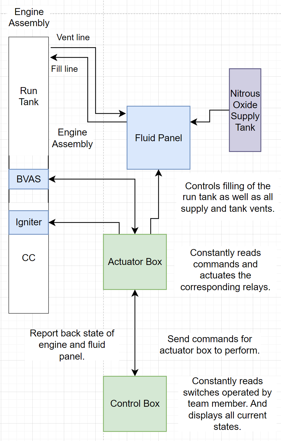
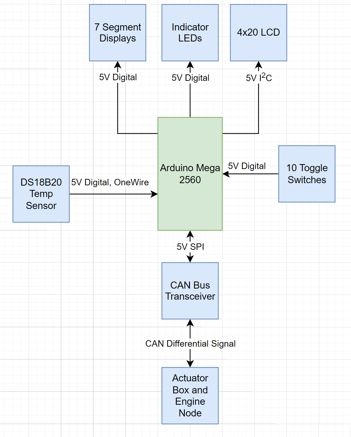
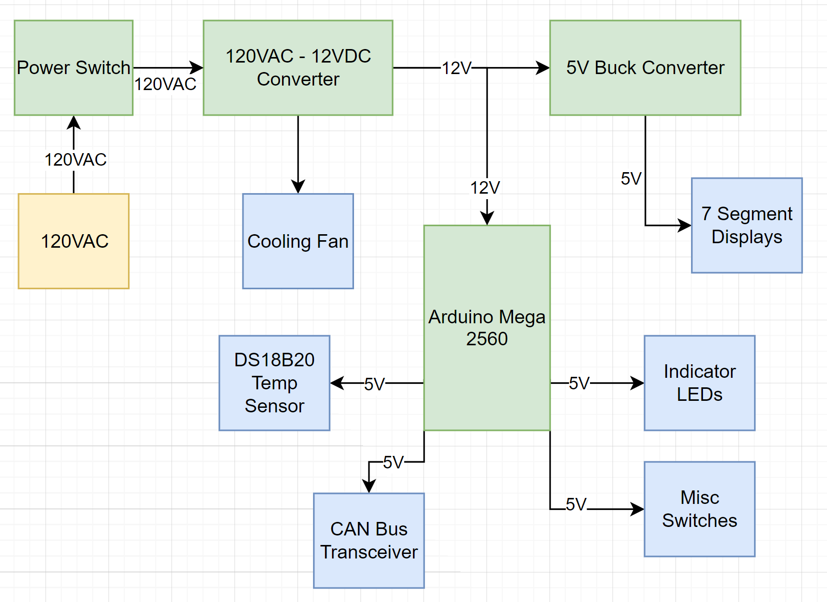
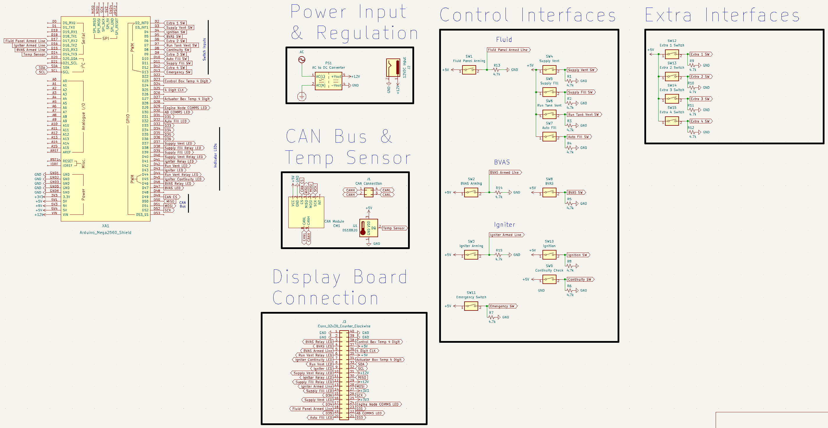
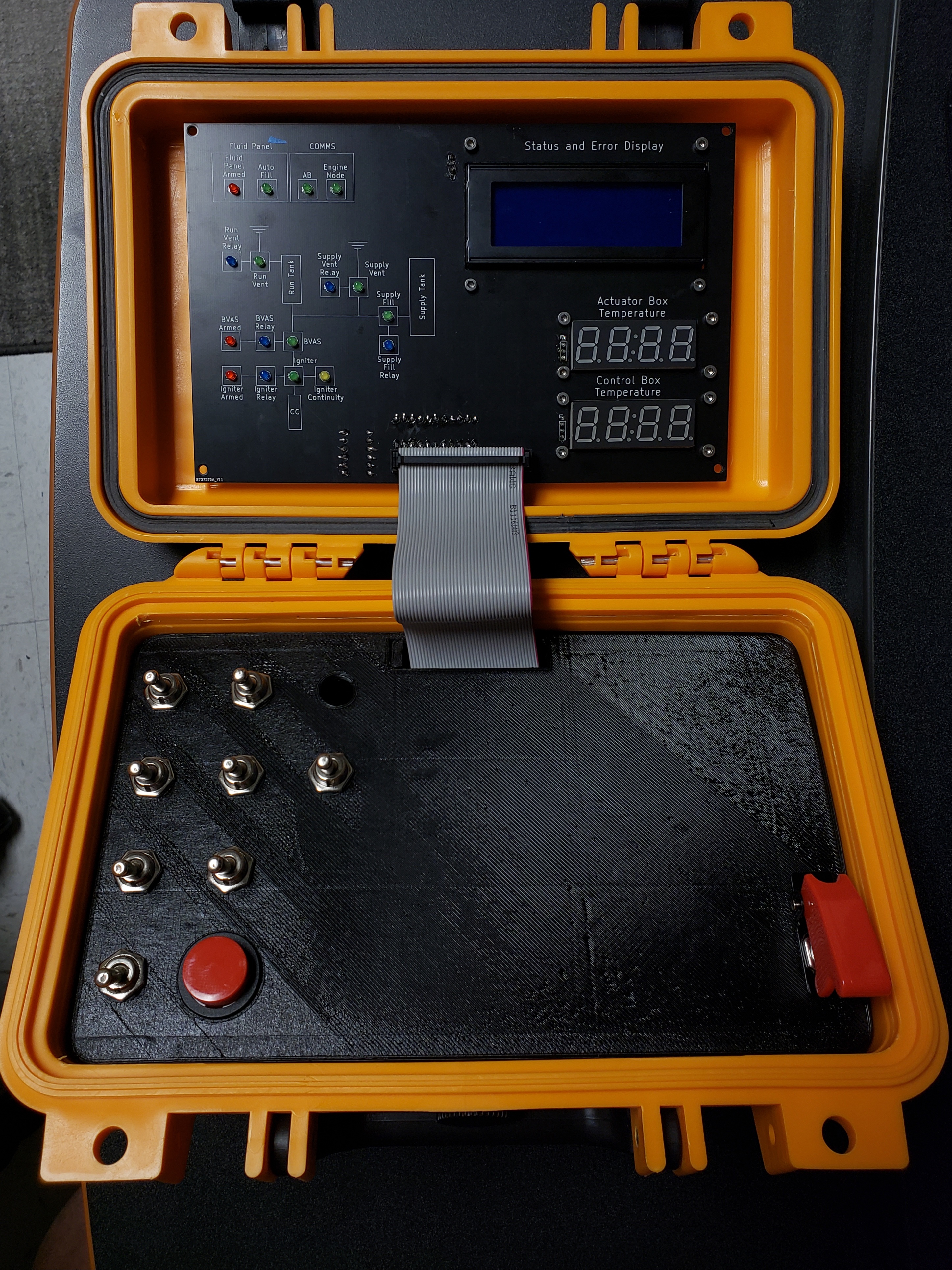
Control Box
The control box is responsible for taking in operator inputs and sending them to the actuator box over CAN. The control box also receives feedback from the actuator box and updates the assortment of LEDs and the LCD screen on the indicator panel.
Logic Diagram
Power Diagram
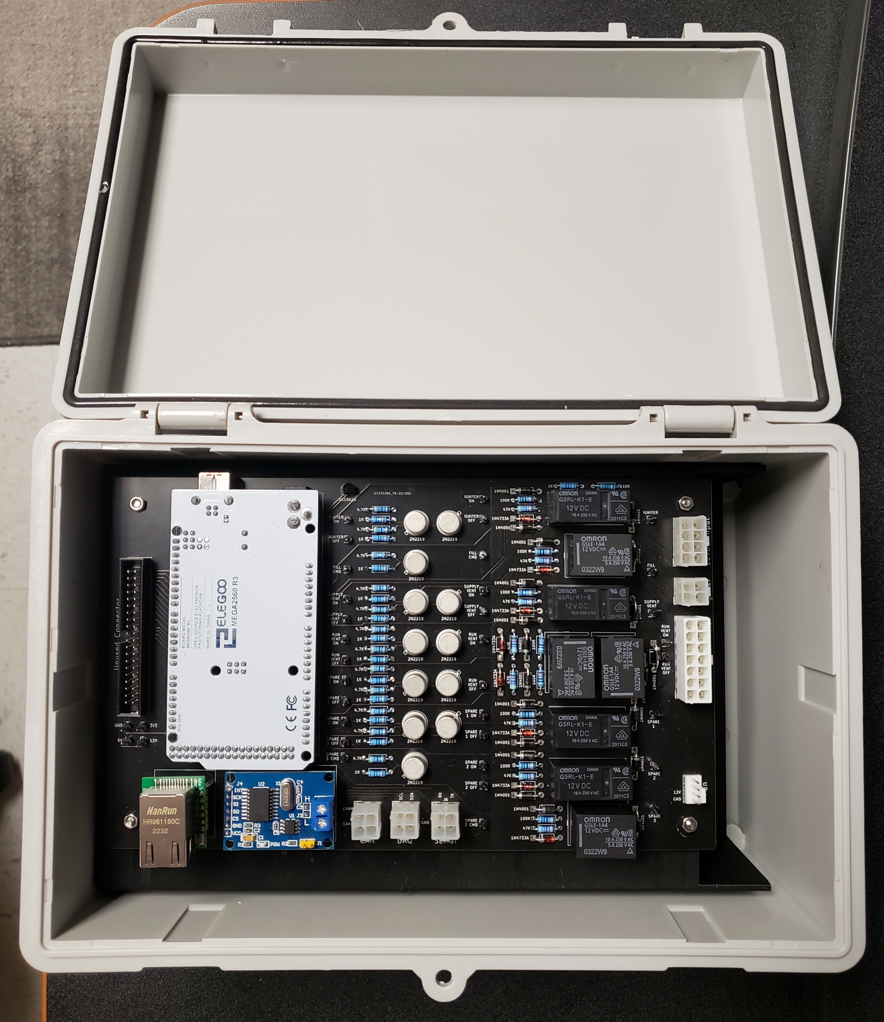
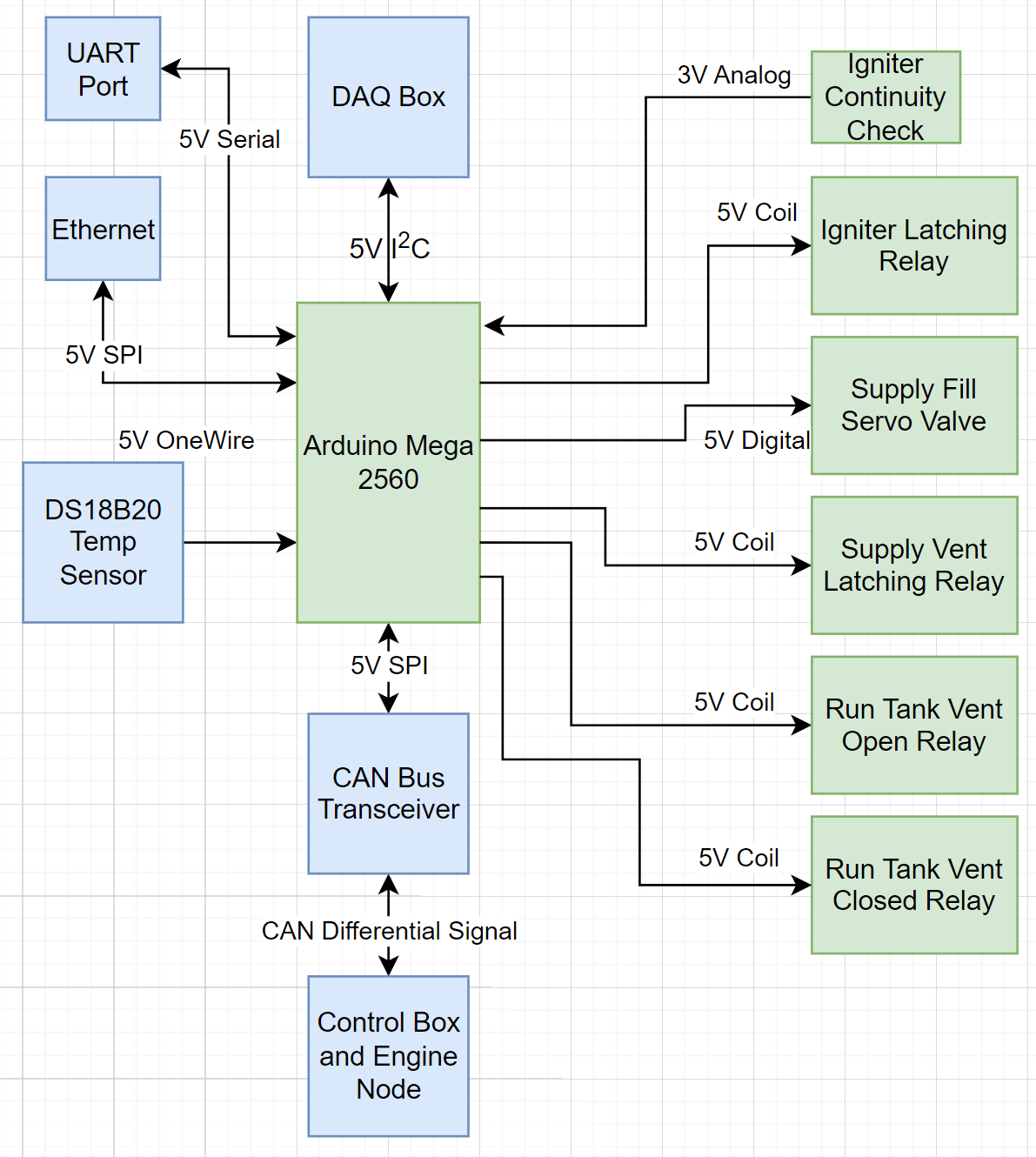
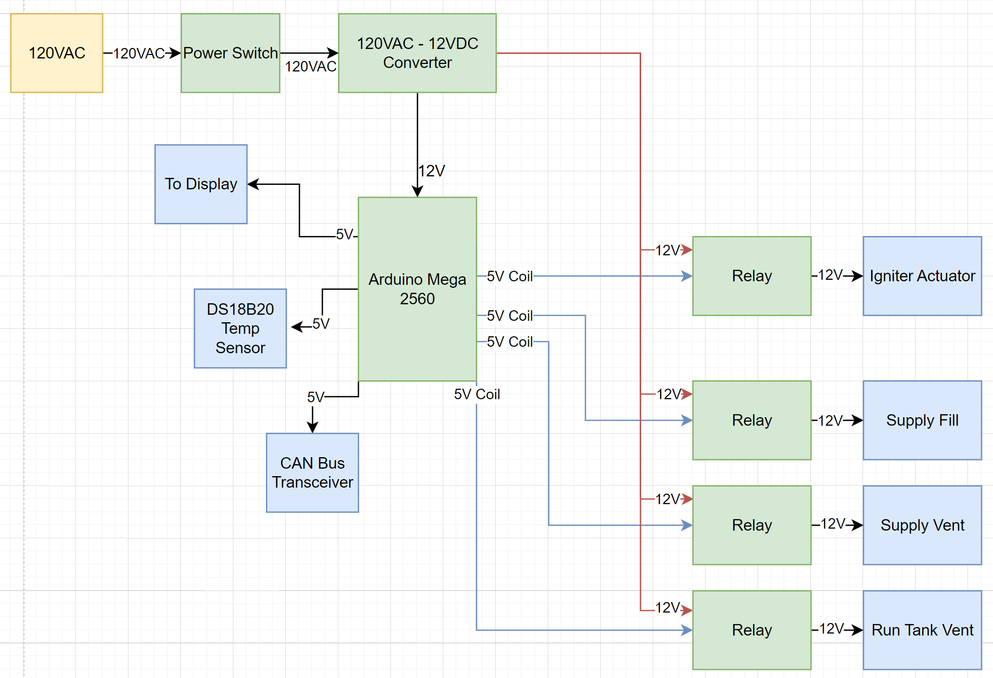
Actuator Box
The actuator box is responsible for actuating valves on the oxidizer fluid panel, main throttle valve on the engine, and igniting the starter system. During a test when avionics is deployed, the avionics stack handles engine control while the actuator box controls ground support systems.
Logic Diagram
Power Diagram
Physical Design
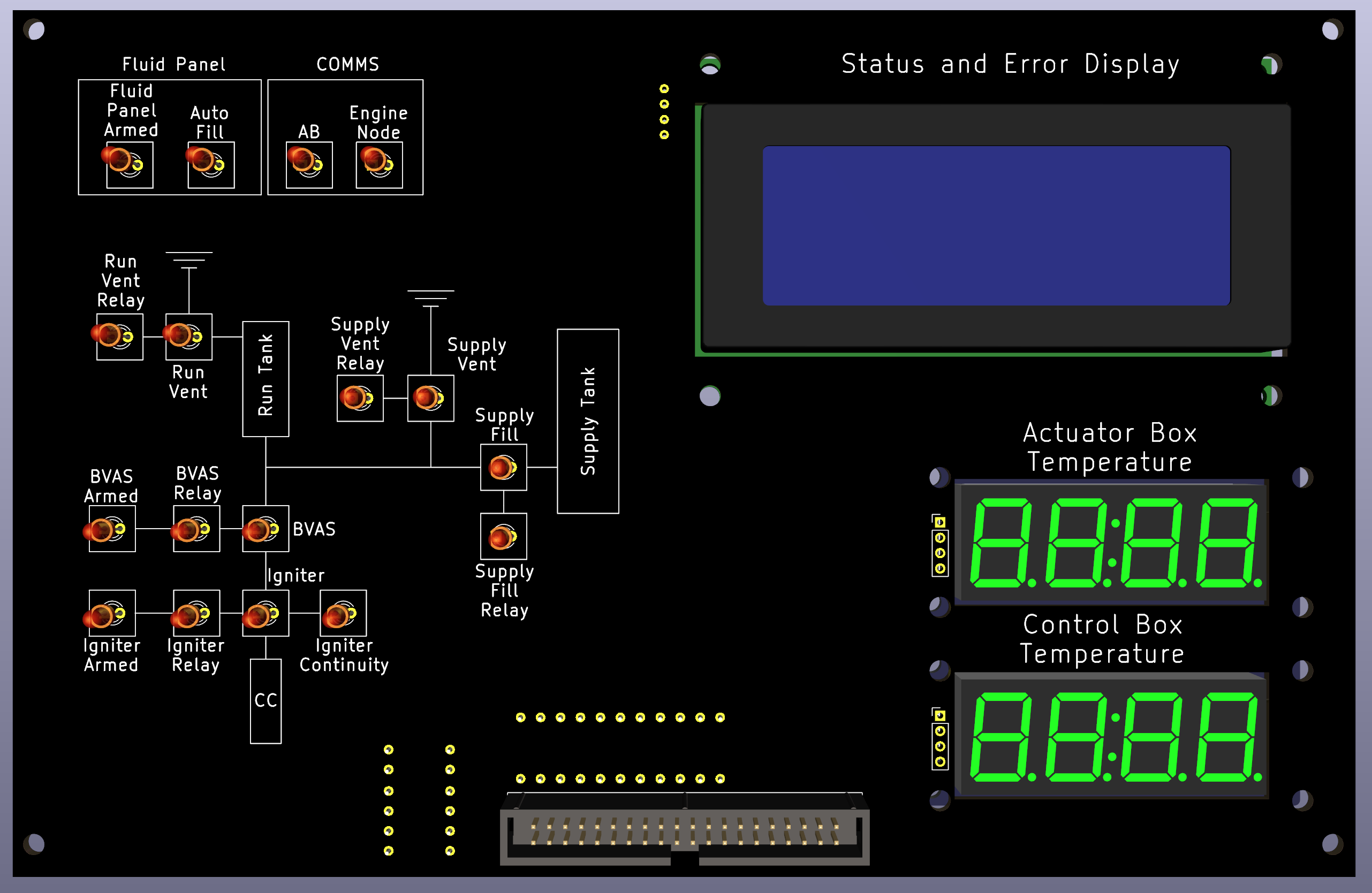
Control Box
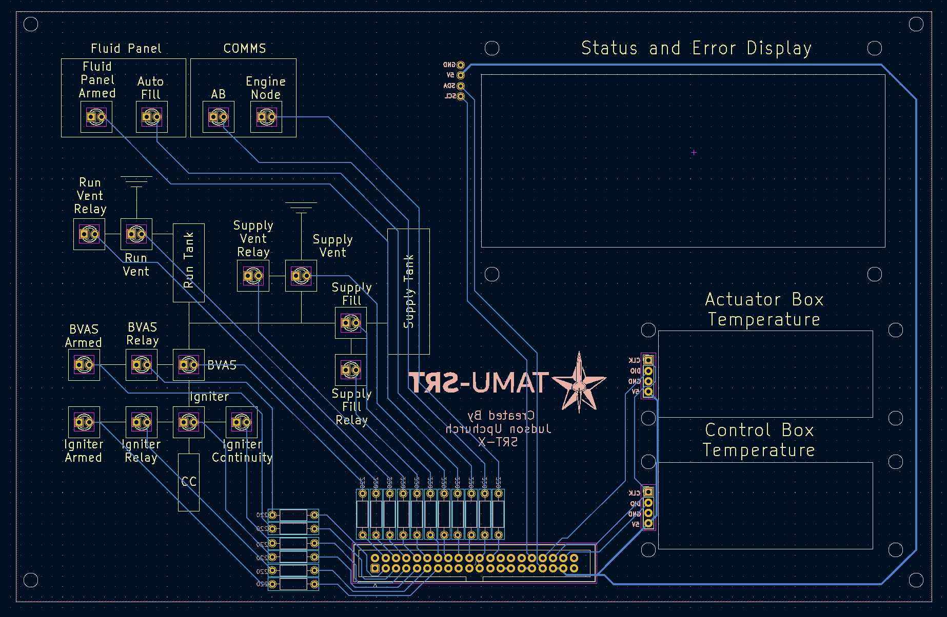
Display PCB
3D Render
PCB Design
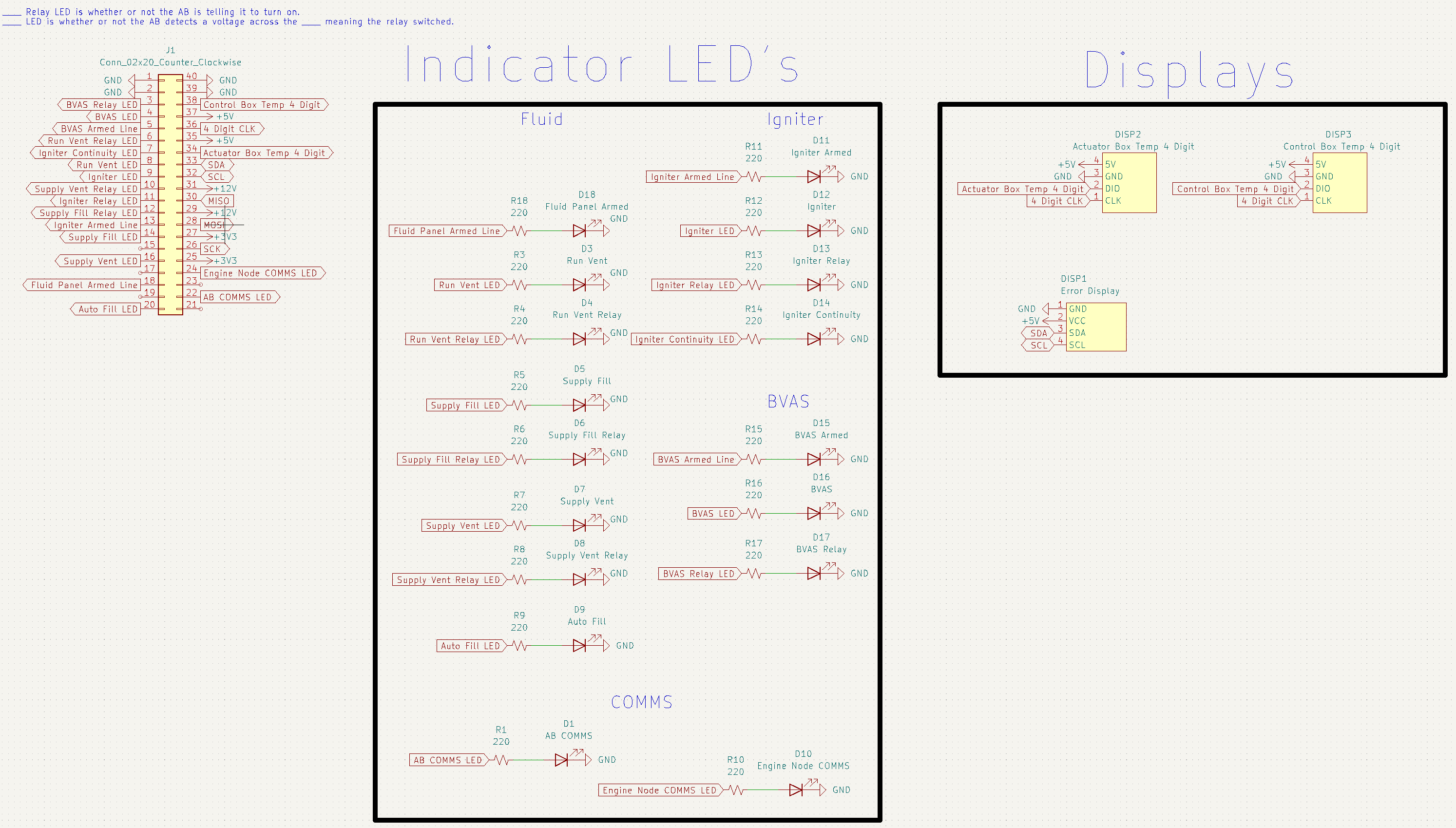
Schematic
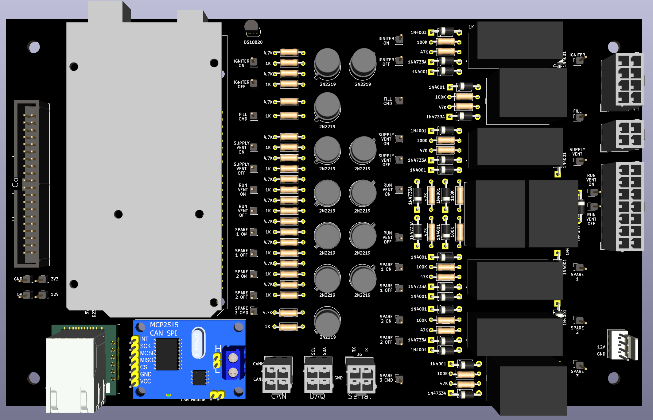
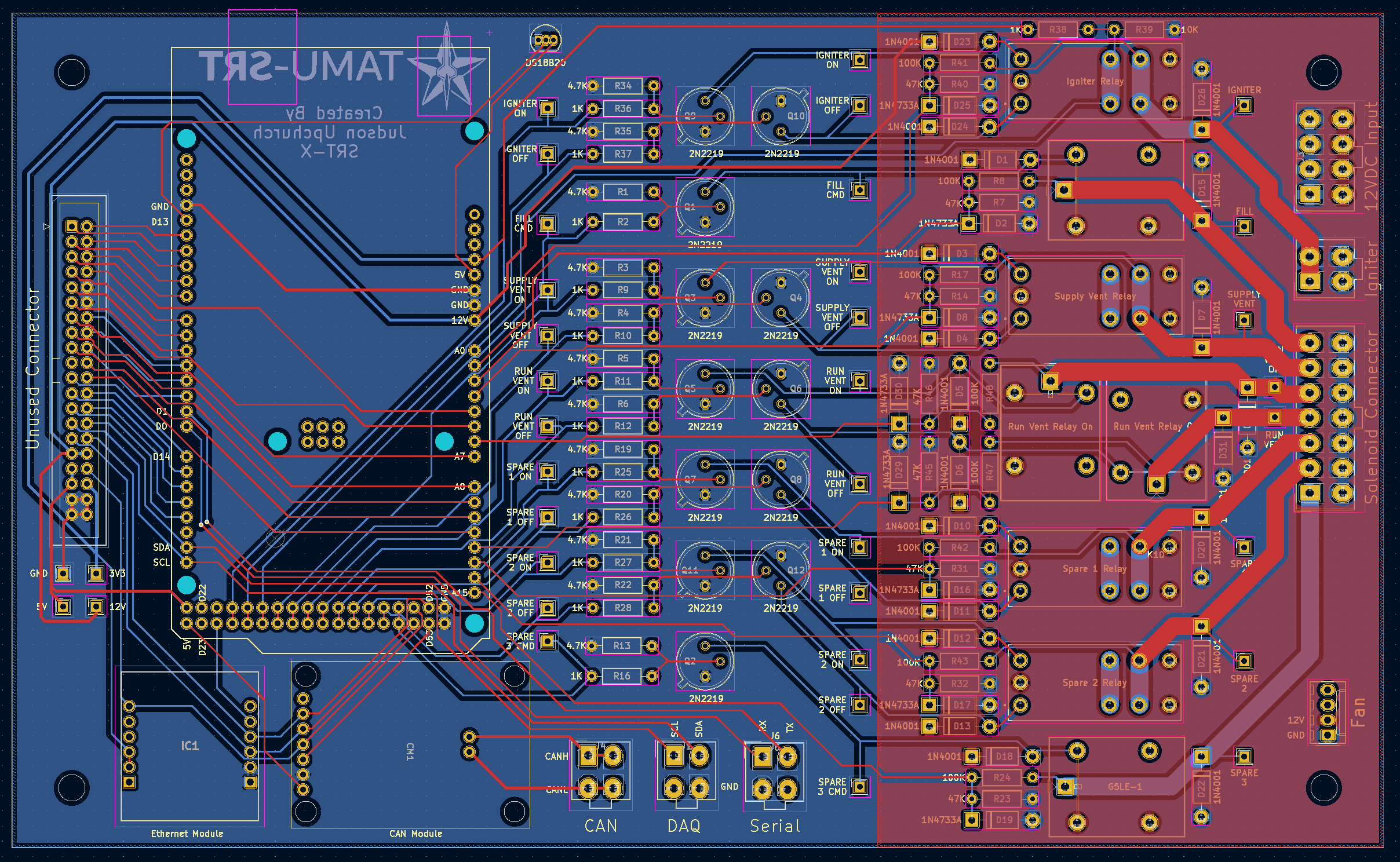
Main PCB
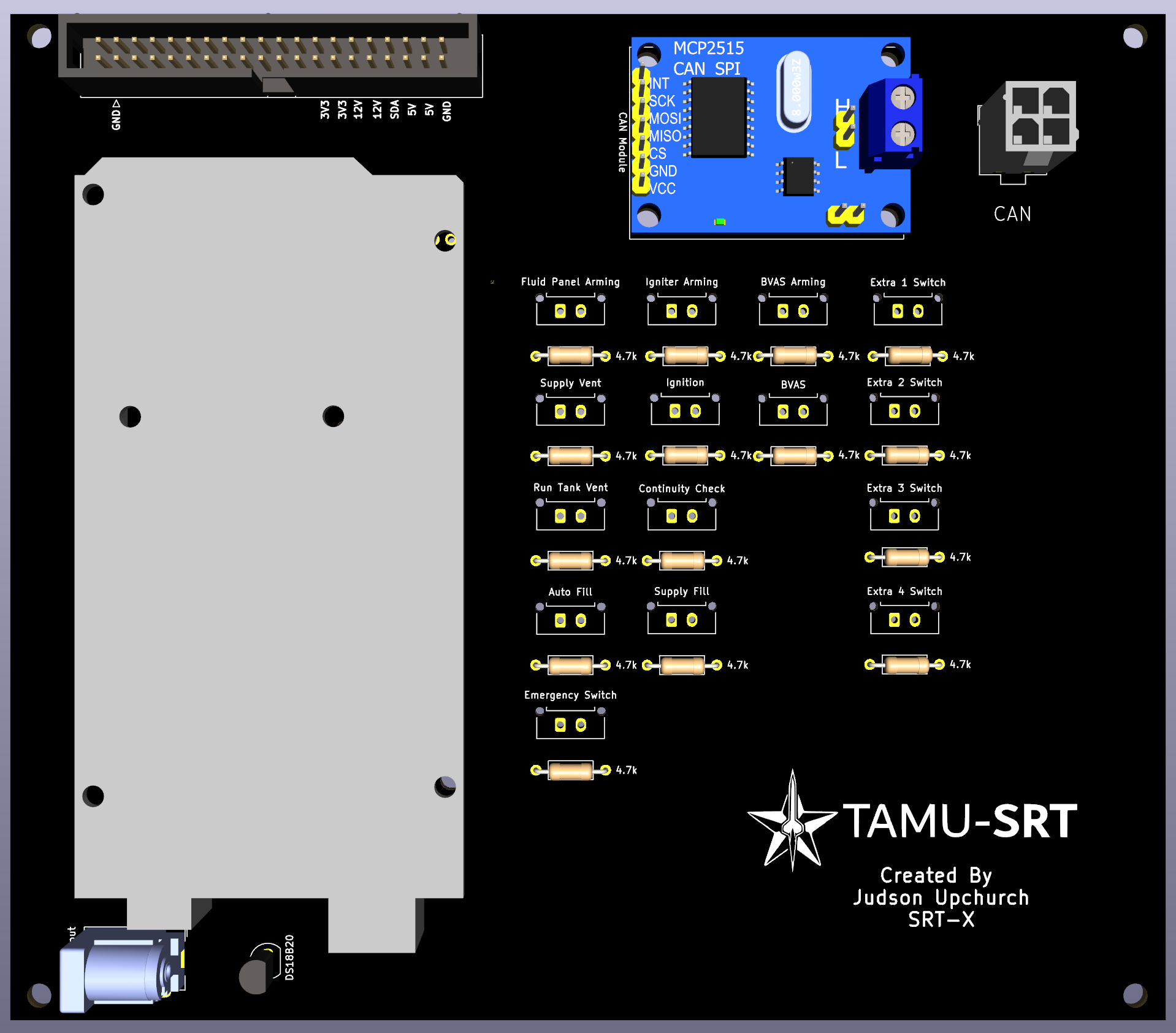
3D Render
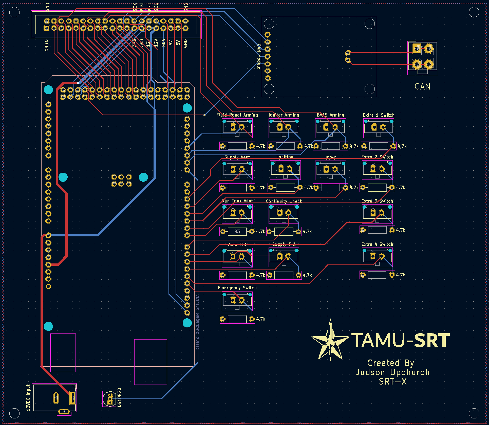
PCB Design
Schematic
Integrated Assembly
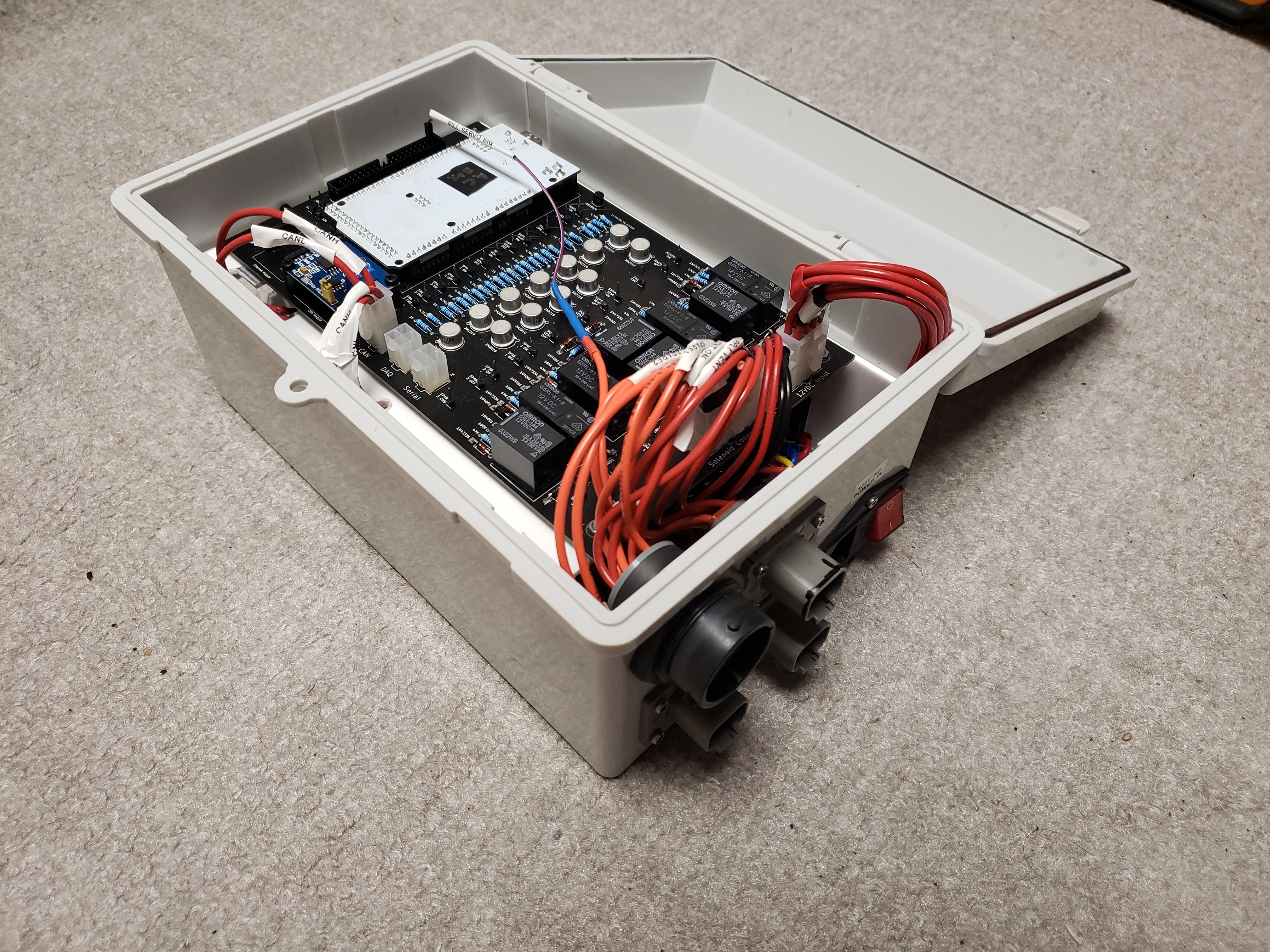
Actuator Box
Actuator PCB
3D Render
PCB Design
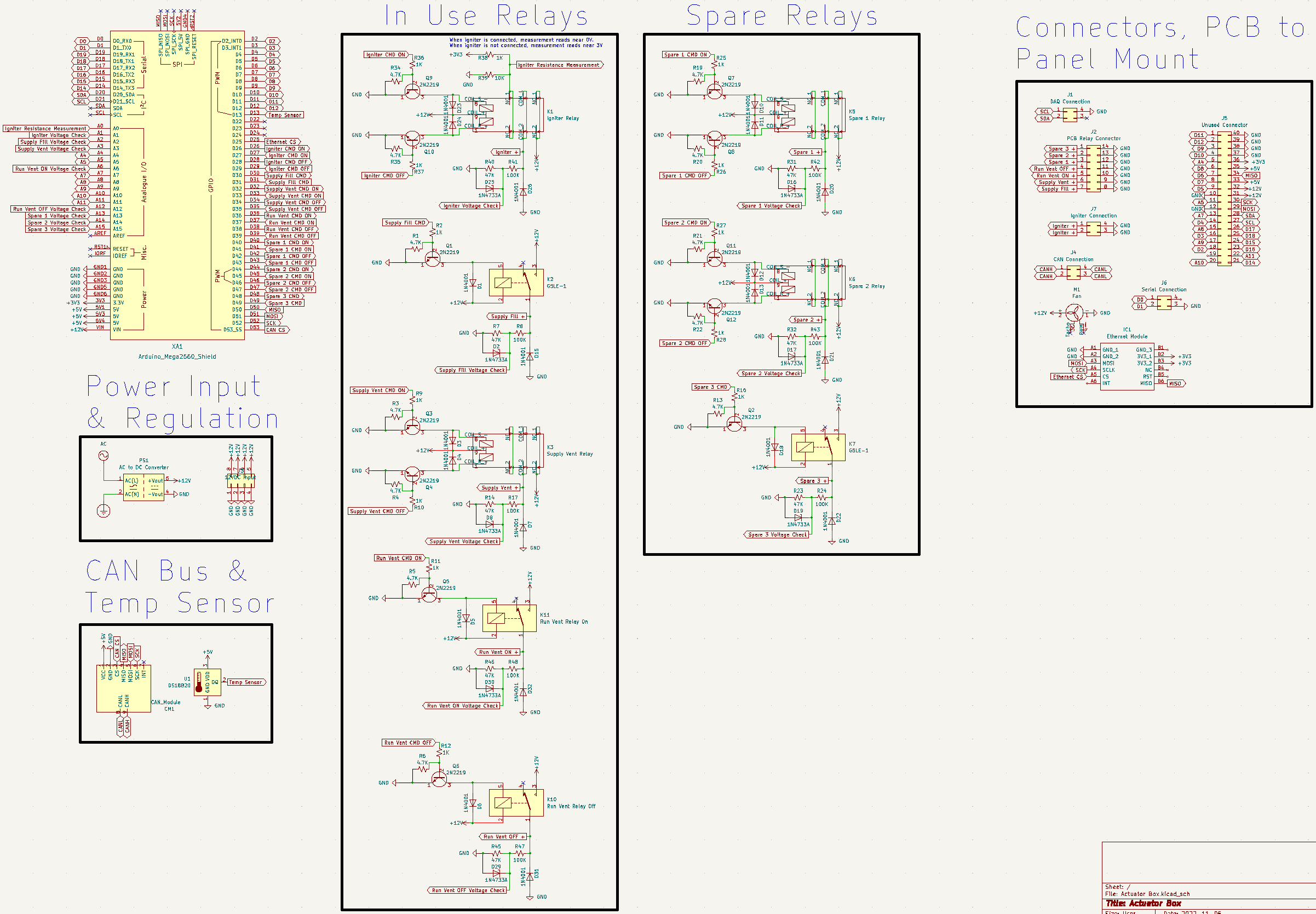
Schematic
Full Schematic
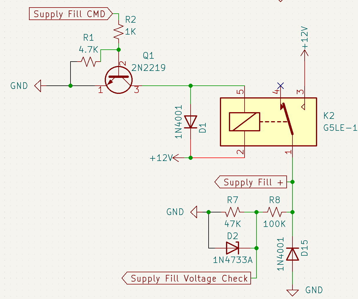
Non-Latching Relay Schematic
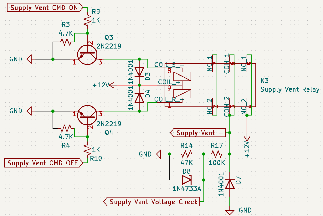
Latching Relay Schematic
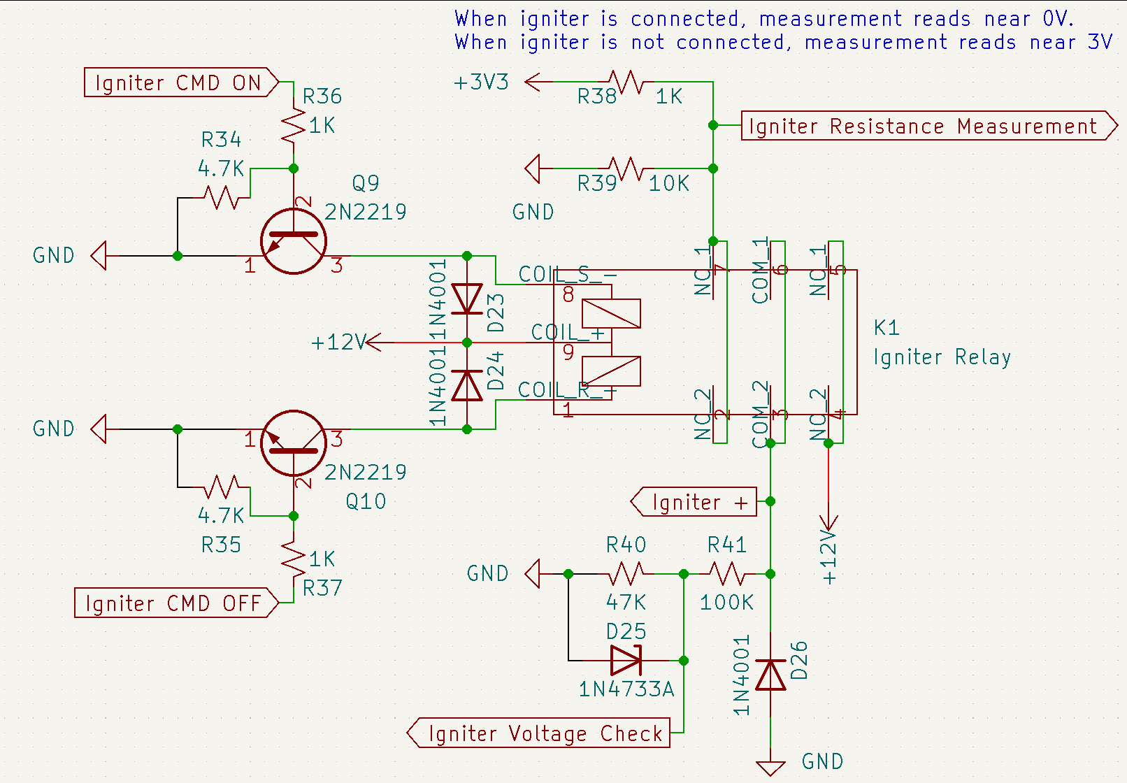
Igniter Relay Schematic
Integrated Assembly