10 KiB
Purpose
The Texas A&M Sounding Rocketry Team designs, builds, and flies its own hybrid rocket. As part of its design cycle, static cold flows and static engine tests are performed to chacterize the engine's oxidizer tank, fluid system, and combustion process.
Overall System Design
During a static engine test, we load solid HTPB fuel into the combustion chamber. As part of the test procedure, we load nitrous oxide into the run tank via the fluid panel. We then ignite the starter, and open the ball valve actuation system (BVAS) to begin our combustion cycle.
Concept of Operation
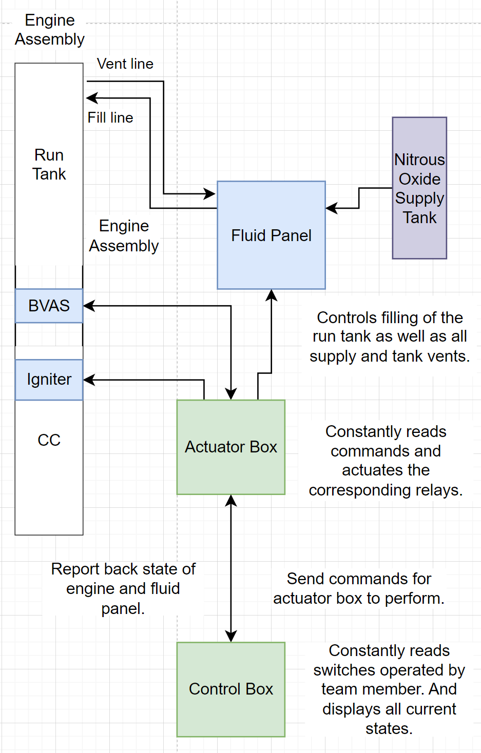
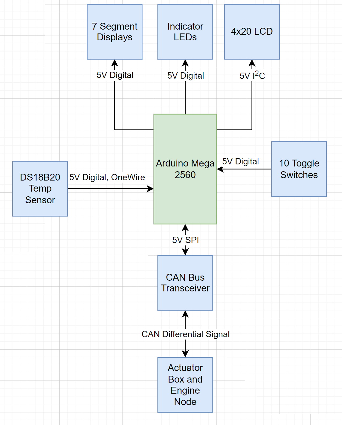
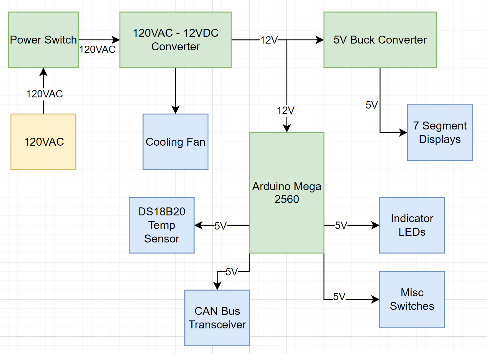
Control Box
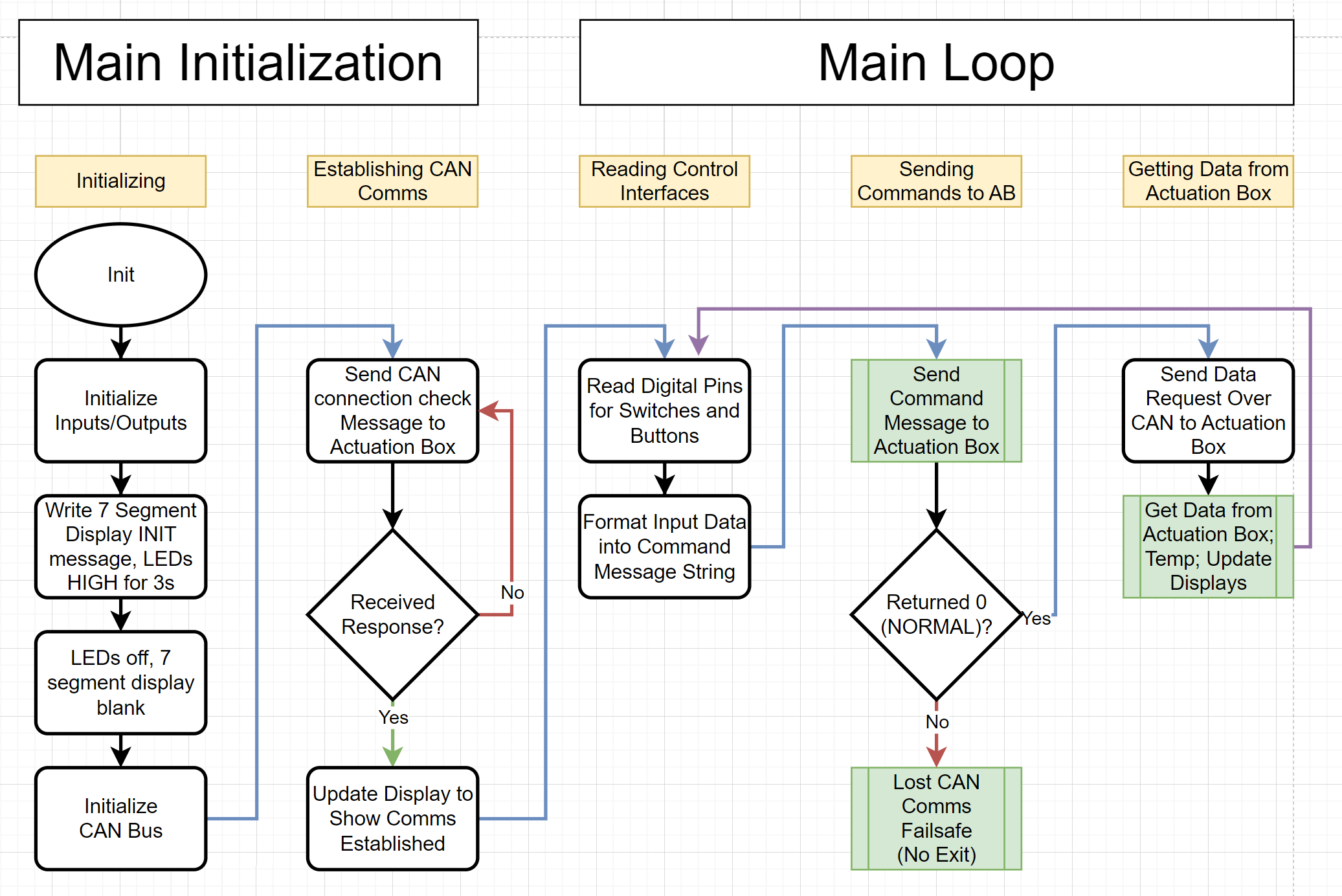
The control box is responsible for taking in operator inputs and sending them to the actuator box over CAN. The control box also receives feedback from the actuator box and updates the assortment of LEDs and the LCD screen on the indicator panel.
Logic Diagram
Power Diagram
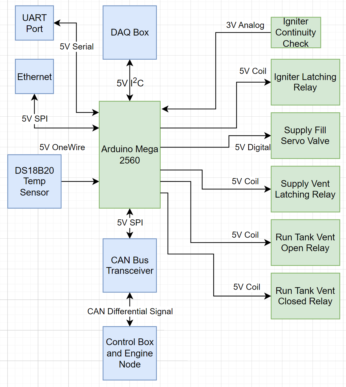
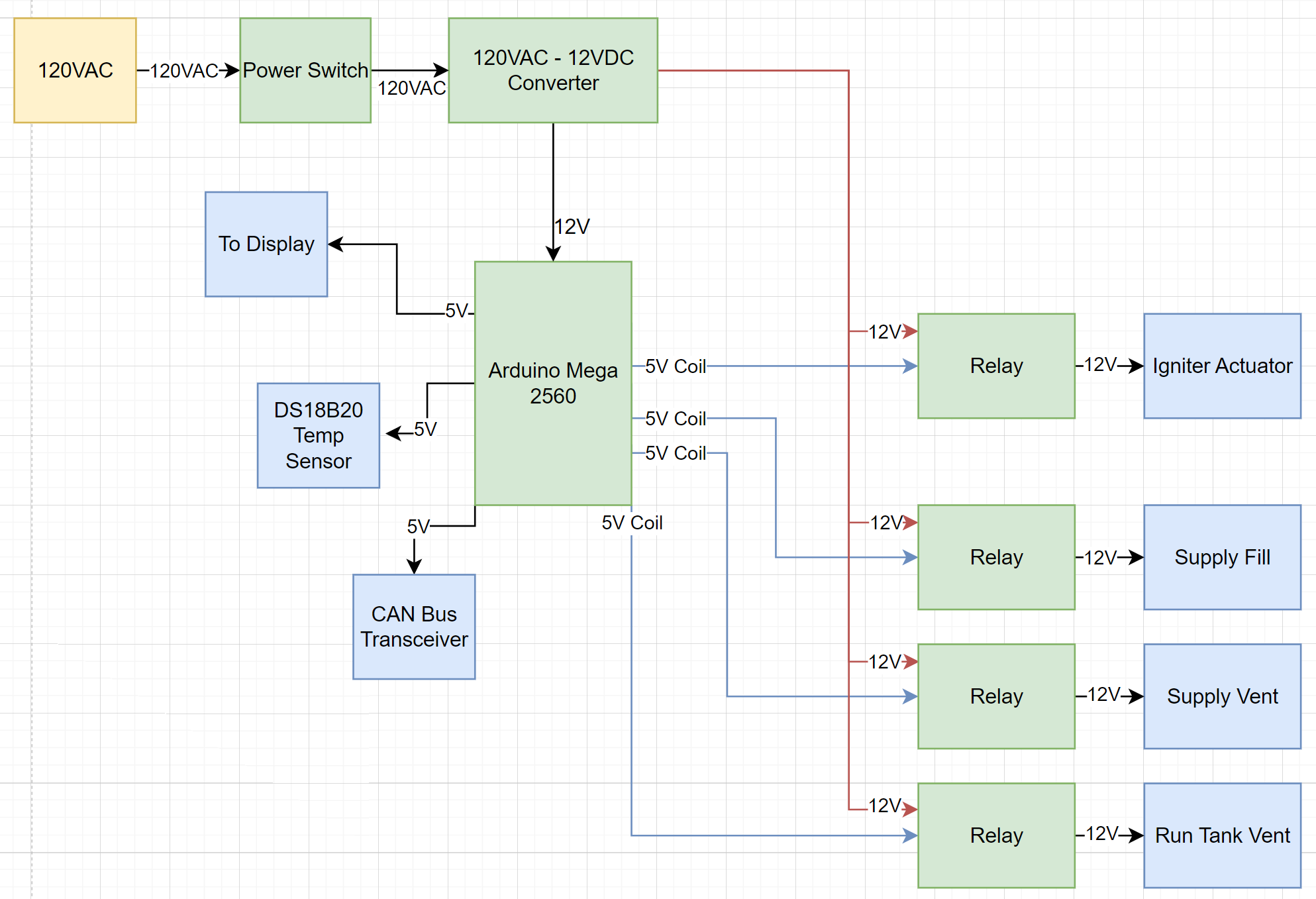
Actuator Box
The actuator box is responsible for actuating valves on the oxidizer fluid panel, main throttle valve on the engine, and igniting the starter system. During a test when avionics is deployed, the avionics stack handles engine control while the actuator box controls ground support systems.
Logic Diagram
Power Diagram
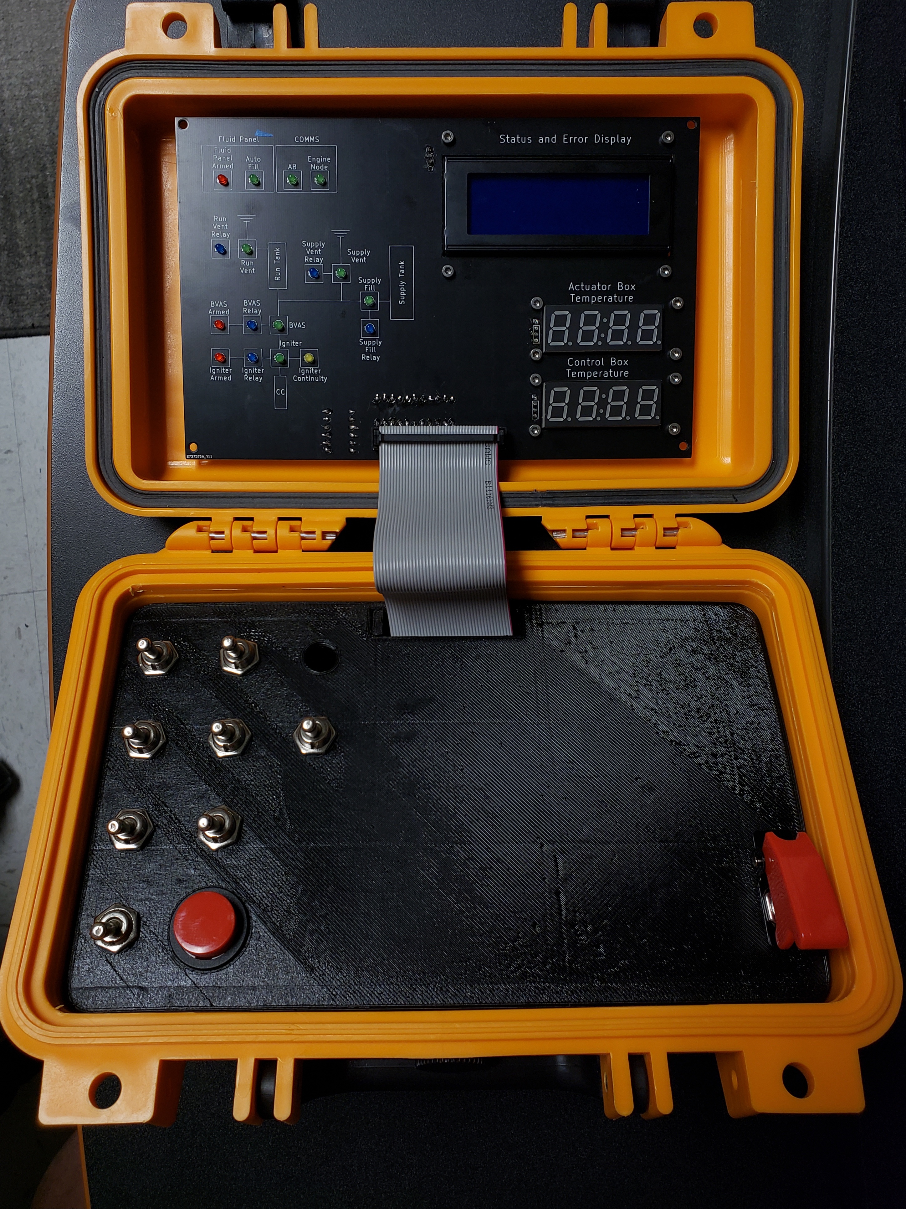
Physical Design
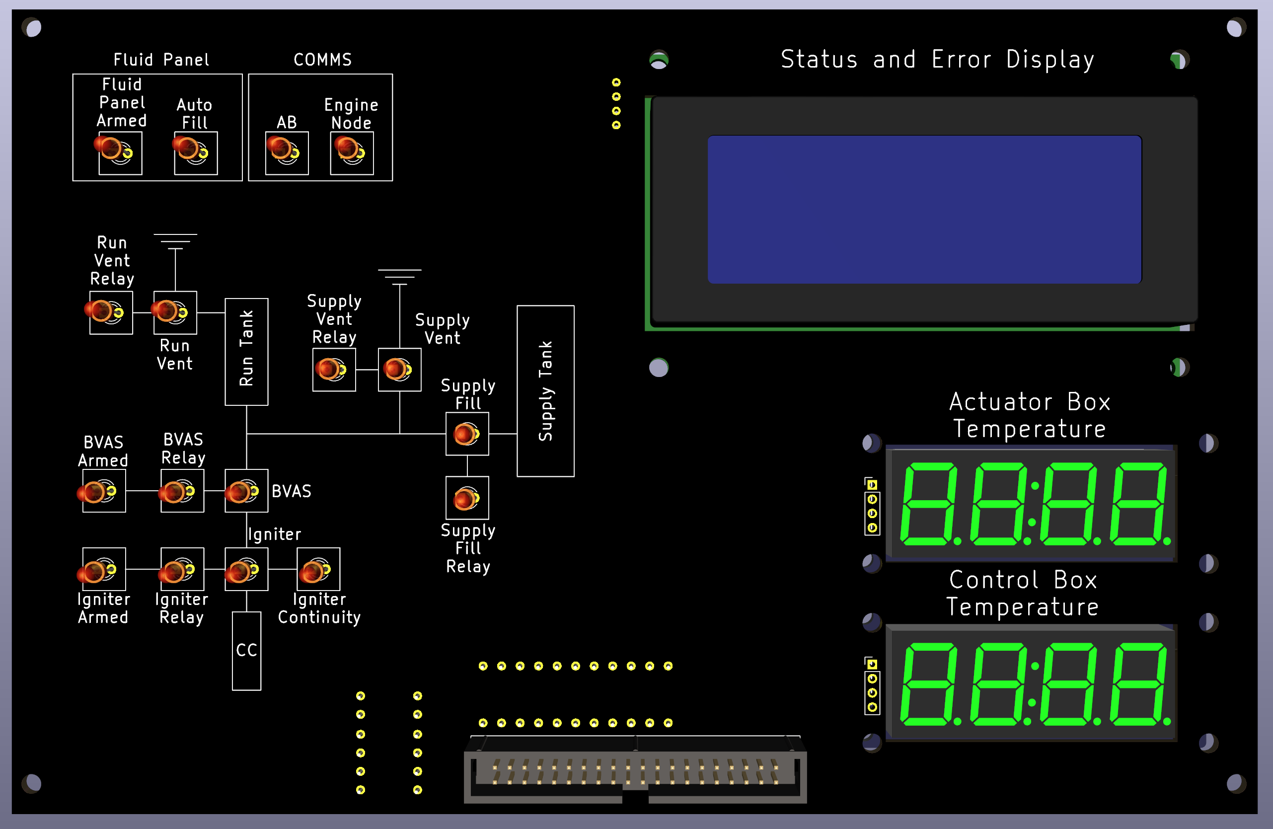
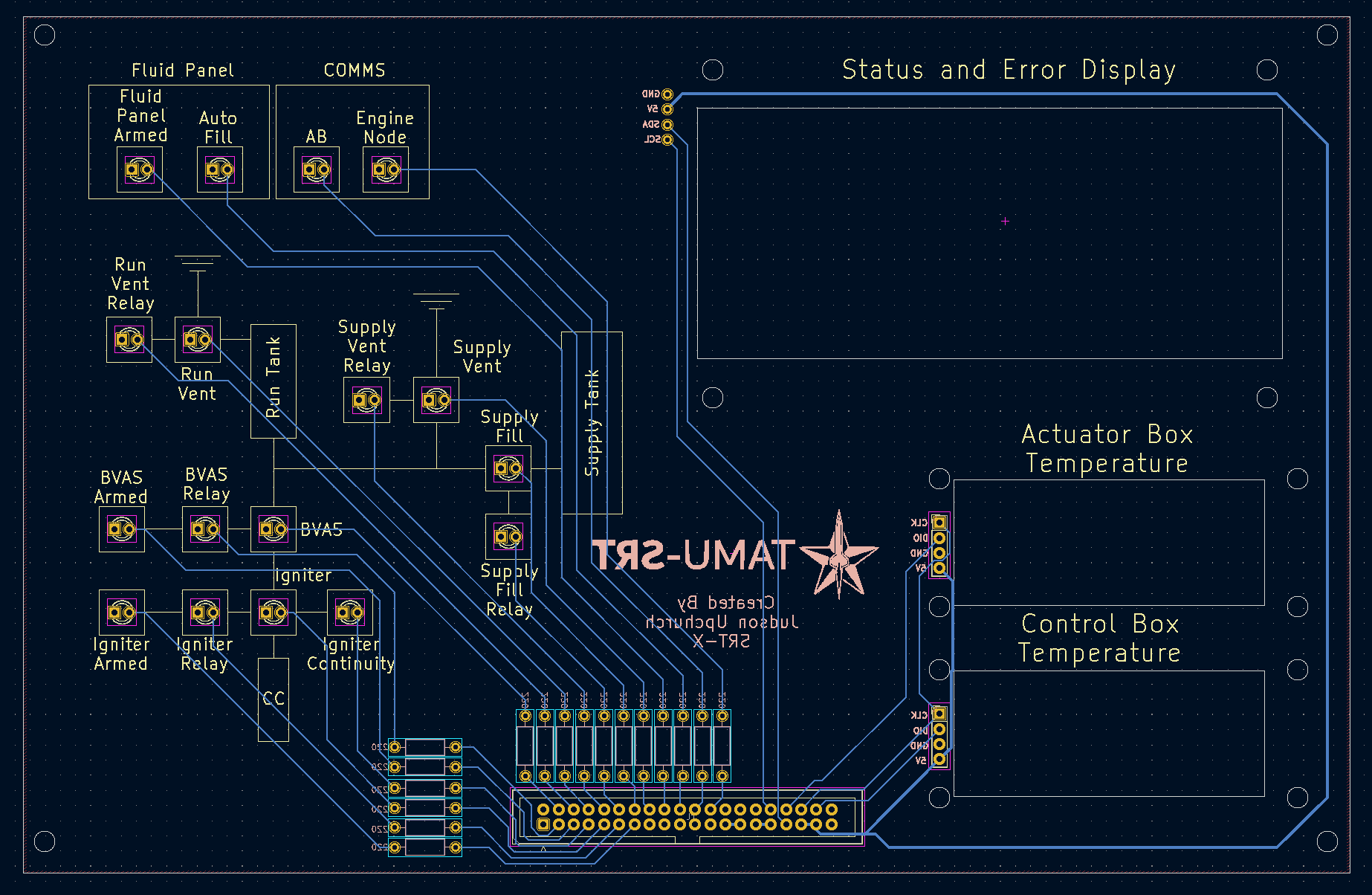
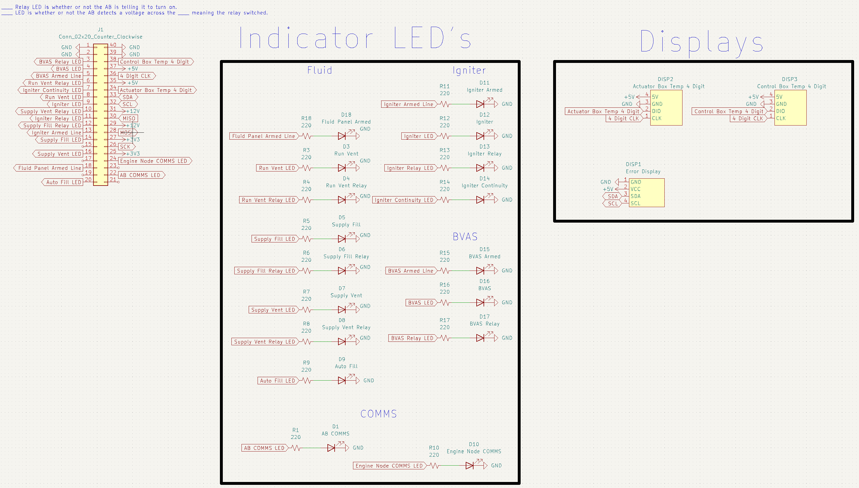
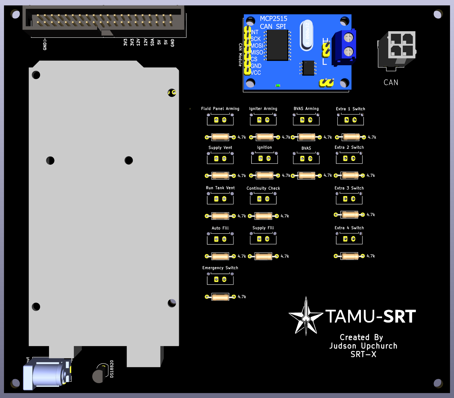
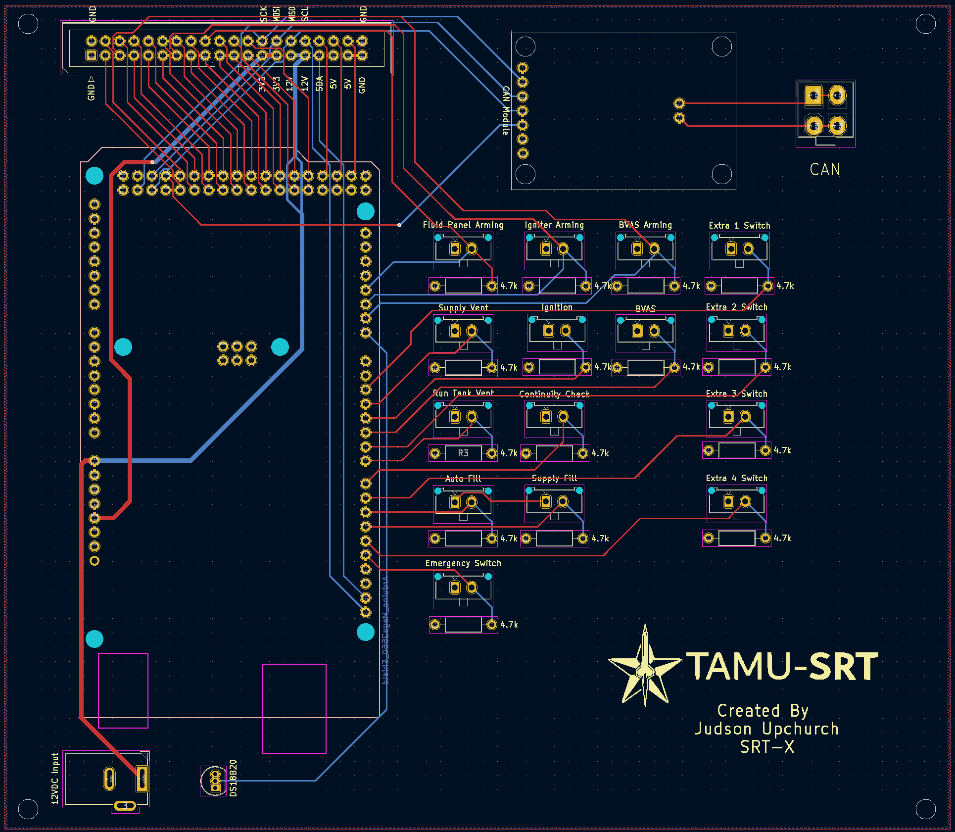
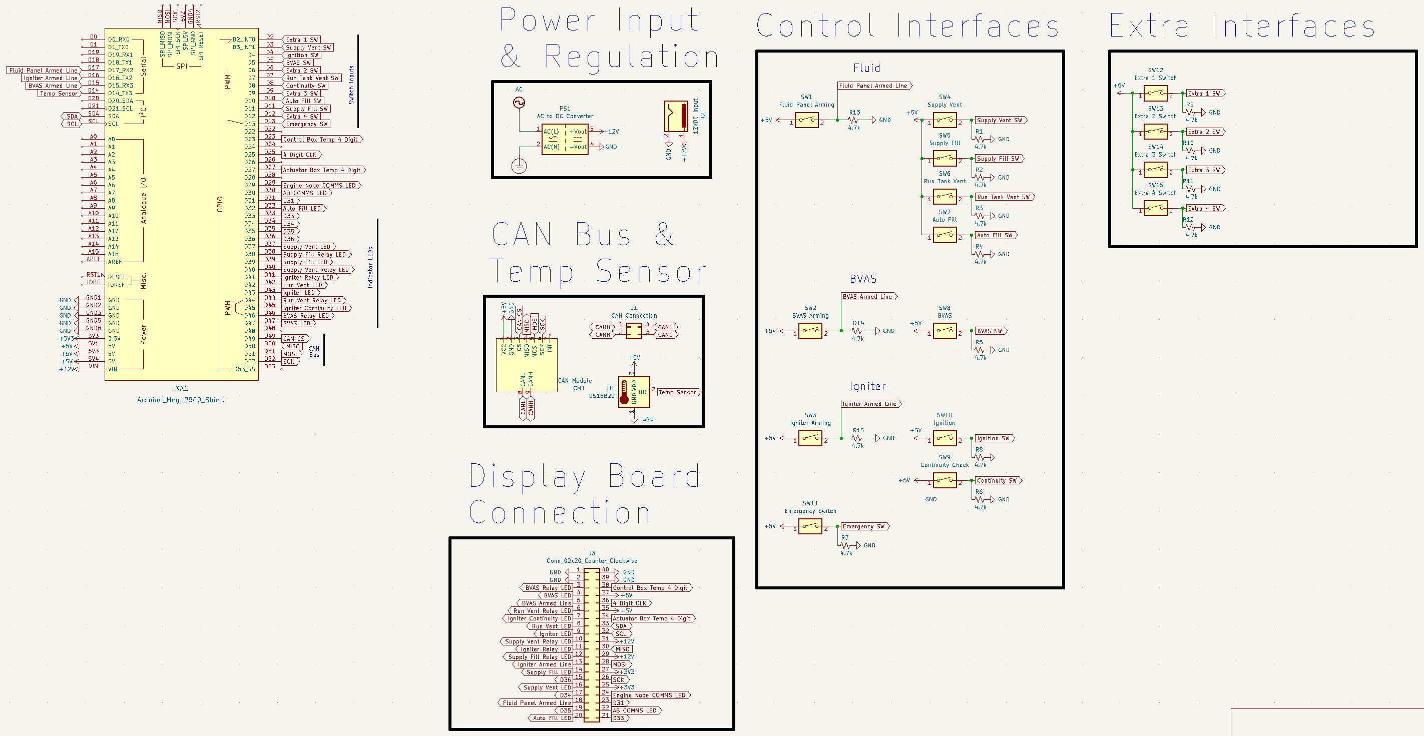
Control Box
Display PCB
3D Render
PCB Design
Schematic
Main PCB
3D Render
PCB Design
Schematic
Integrated Assembly
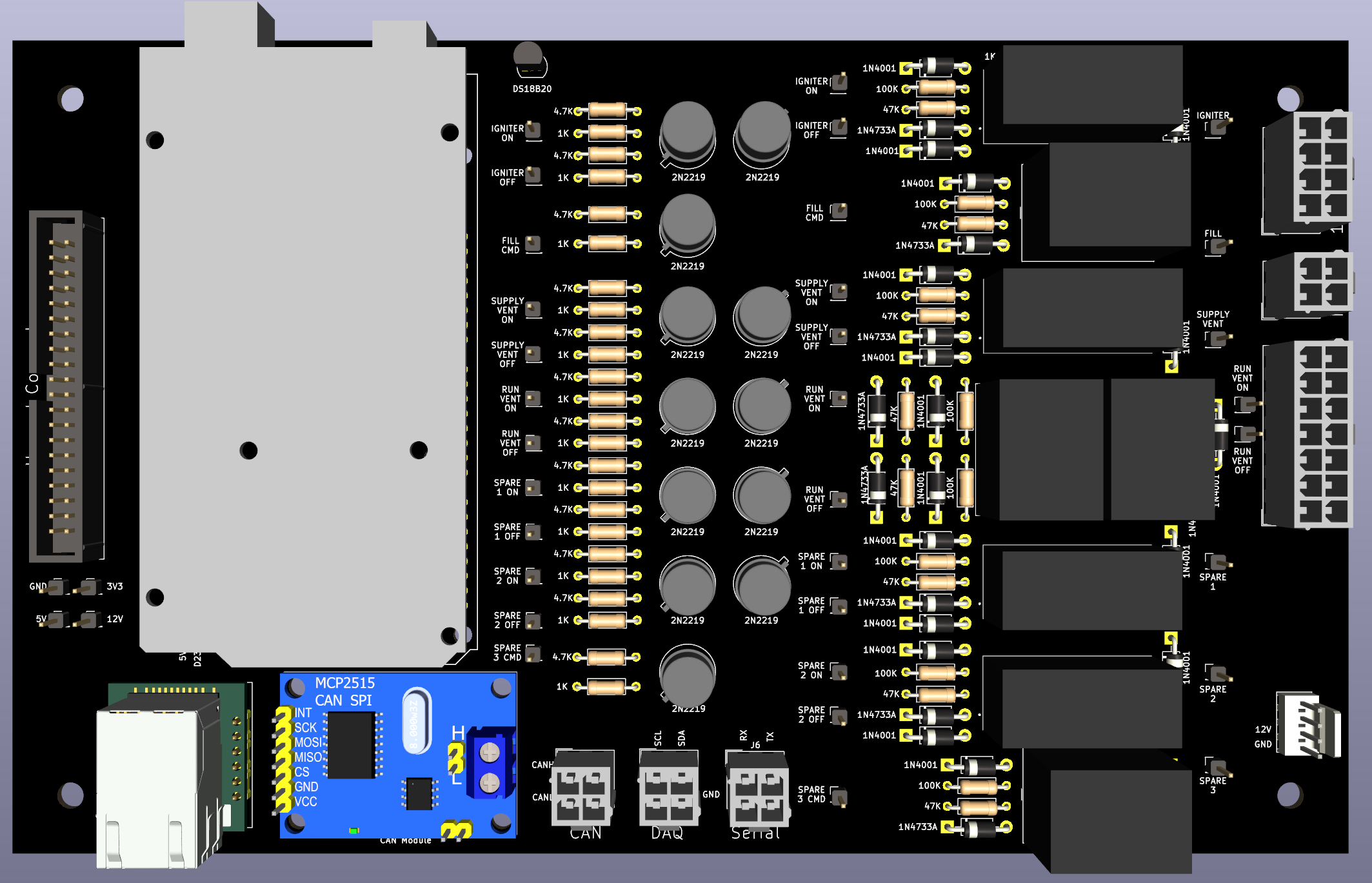
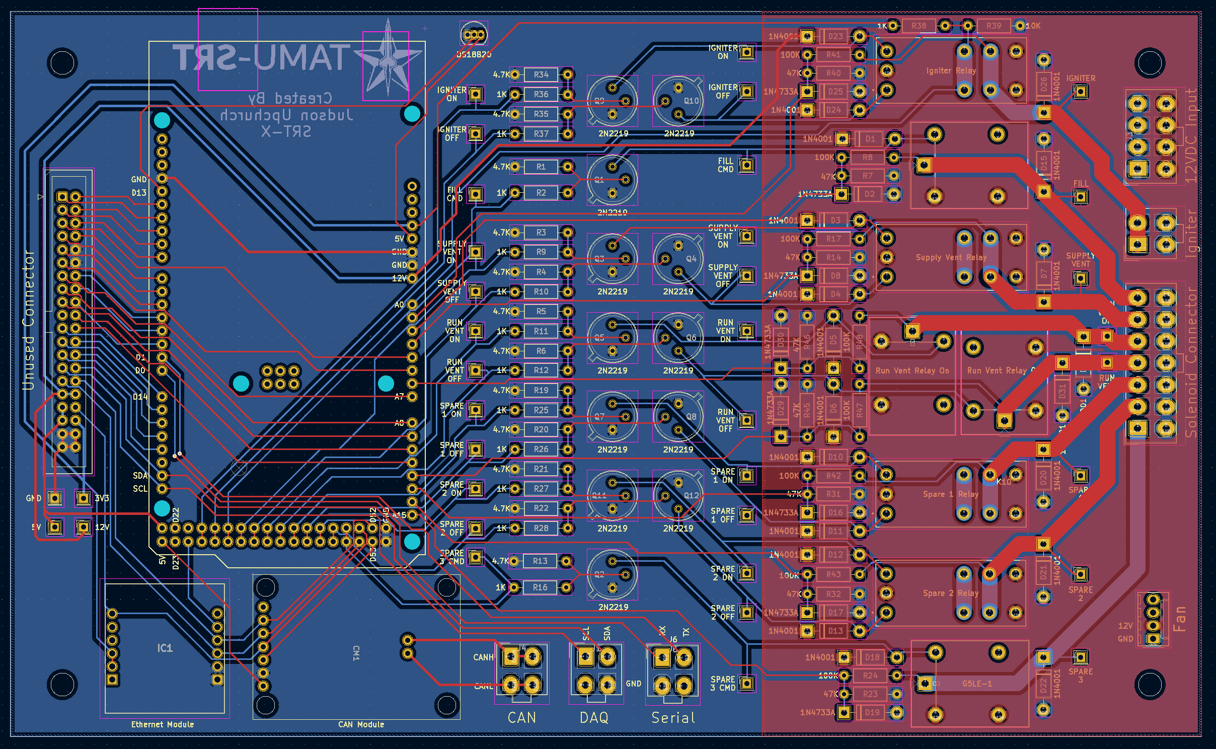
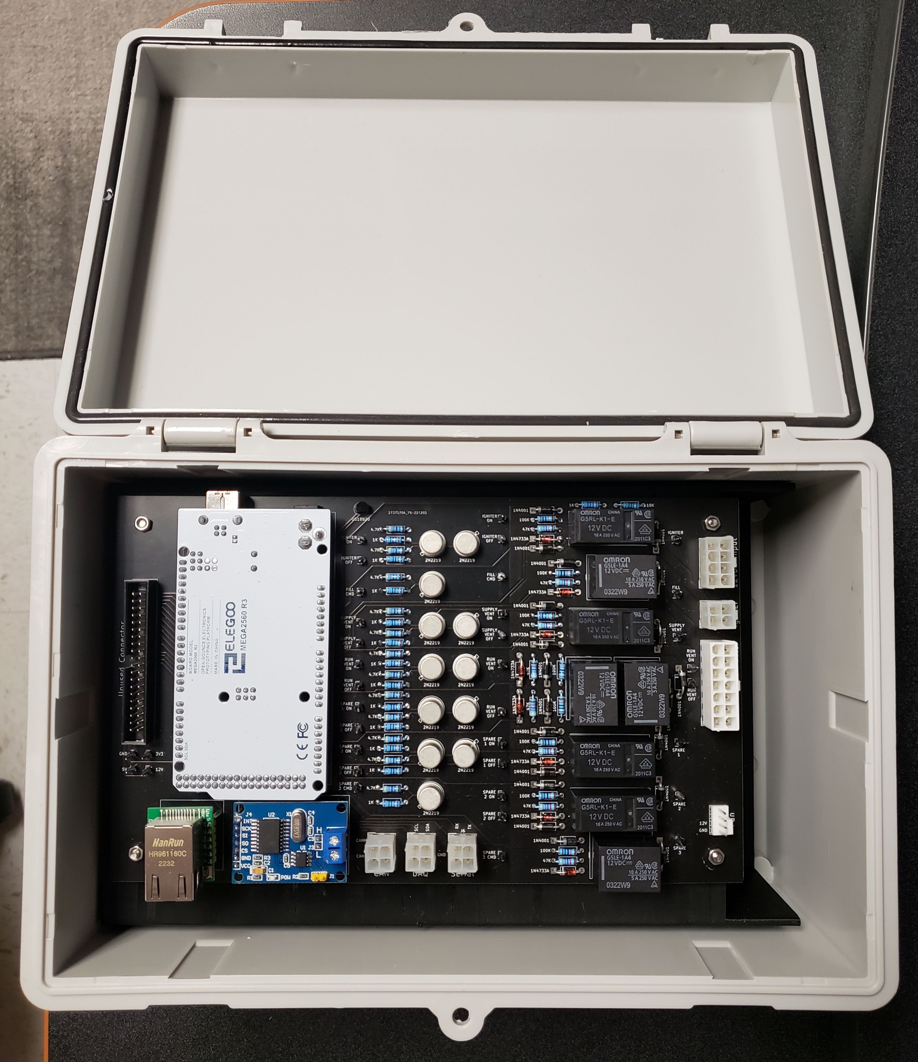
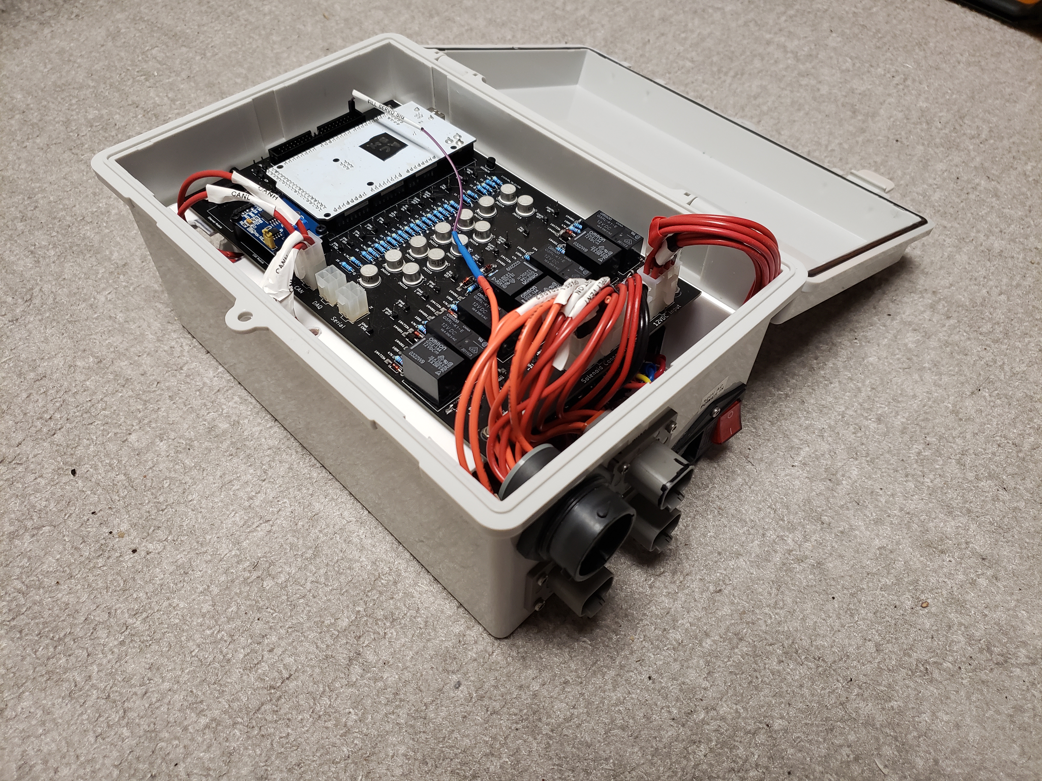
Actuator Box
Actuator PCB
3D Render
PCB Design
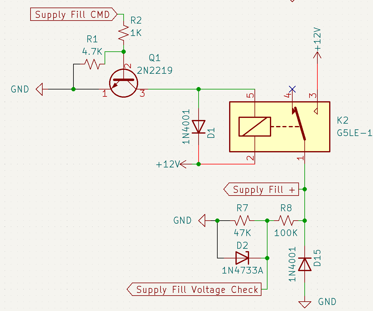
Schematic
Full Schematic
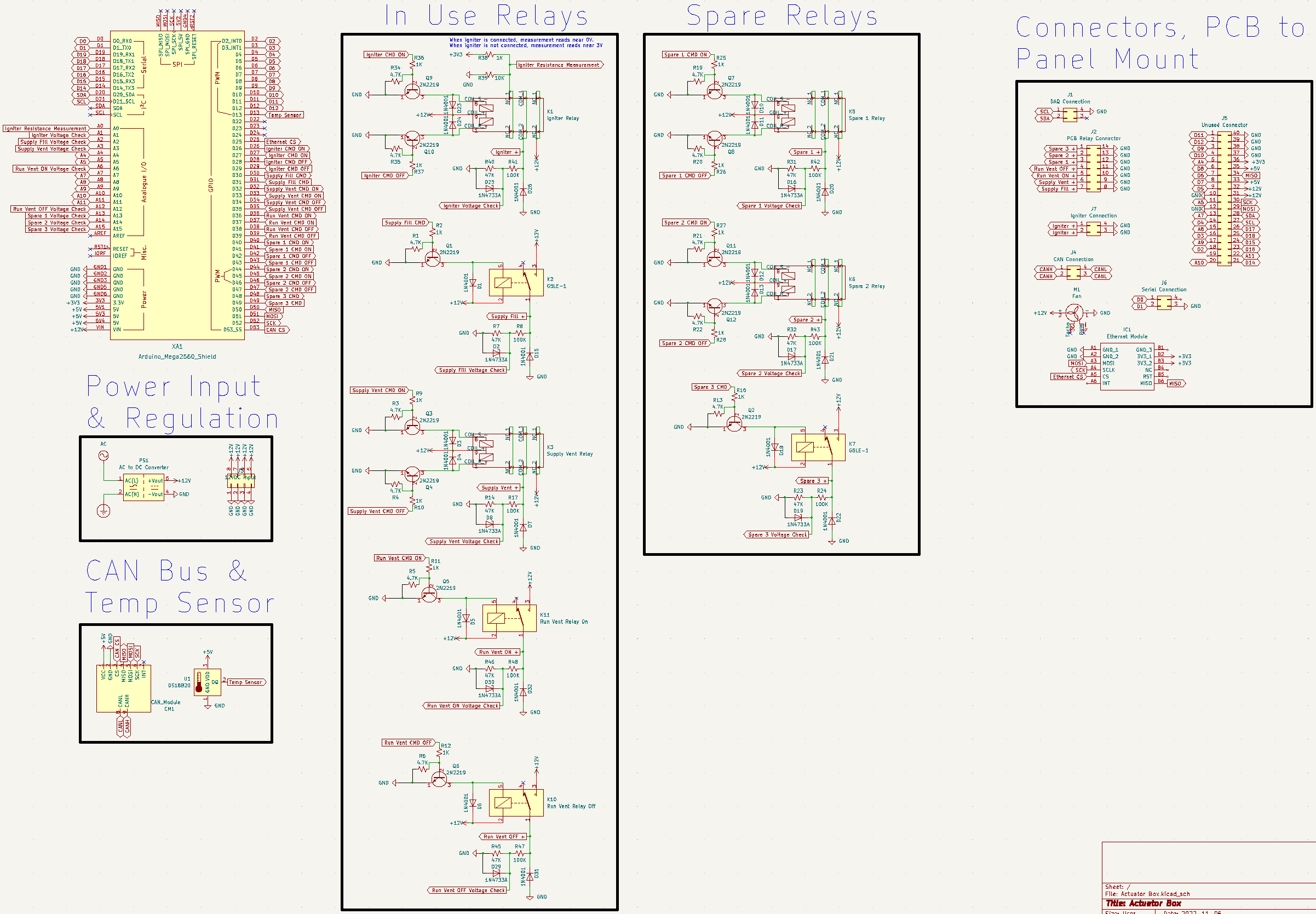
Non-Latching Relay Schematic
Latching Relay Schematic
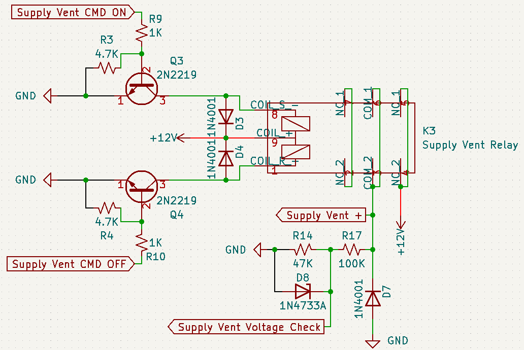
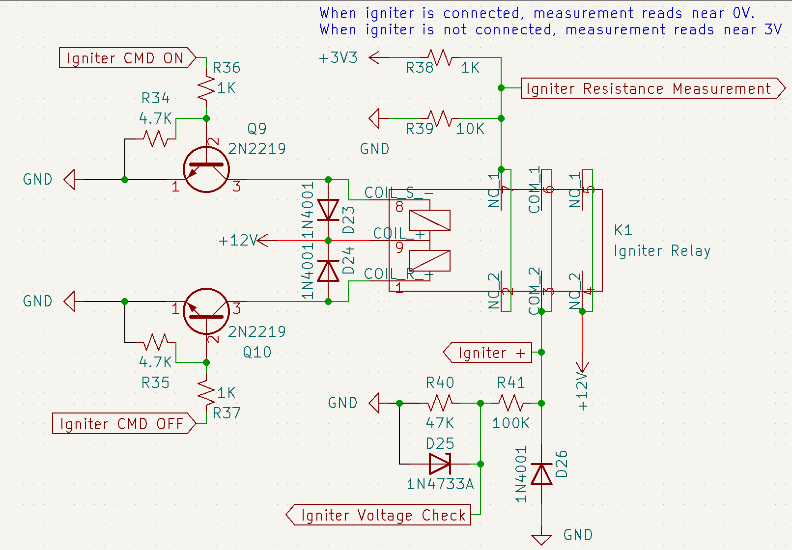
Igniter Relay Schematic
Integrated Assembly
Arduino Software
Common Software
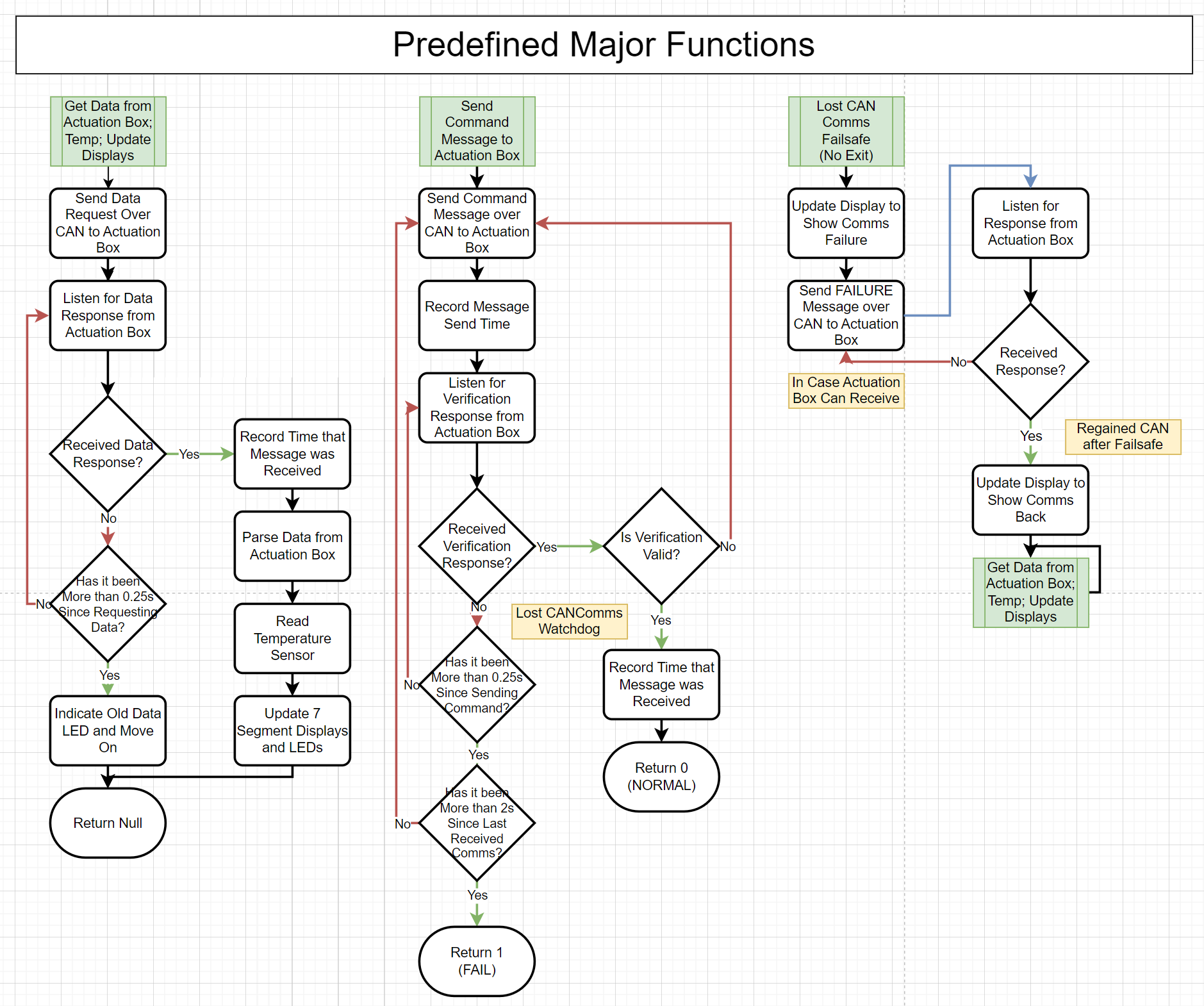
CAN Comms
For the peer to peer communication between the Control Box and the Actuator Box, the Controller Area Network (CAN) Bus was chosen for its amazing signal integrity and simple to use libraries with Arduino. Key features in this use case are the 8 byte frames sending unsigned chars and the can_id unsigned integer which designates the type of packet being sent.
On startup (and communication loss from a power outage, random restart, or CAN harness disconnect), the devices go through a 2-way handshake that consists of the control box sending a ping, the actuator box replying to the ping, and the control box acknowledging the reply.
For the packet structure, the formatting can be found here.
Control Box
Logic Diagram
Custom LCD Class
To help manage the text on the 20x4 LCD, a custom class was created.
class LCD {
    private:
        // An array of strings. Each element represents what is currently being shown on the row
        String current_text[4] = {"", "", "", ""};

        // What we will want to update the LCD with
        String desired_text[4] = {"", "", "", ""};

        // Keep track of any blank lines
        bool blank_rows[4] = {true, true, true, true};

    public:
        LCD();

        // Clear the entire LCD
        void clear_lcd();

        // Clear only the line as specified in int row (indexed at 0)
        void clear_lcd_line(int row);

        // Update the physical LCD with the text stored in self->desired_text
        void set_lcd_to_desired_text();

        // Add a string to the self->desired_text arraw at the specified row
        int add_string_to_desired_text(String to_add, int row = -1);

        // Helper function to check string is in self->desired_text
        int check_if_already_in_desired_text(String to_add);

        // Clear the self->desired_text
        void clear_desired_text(int row = -1);
};
LED Groups Based on Relay Type
With the display board having multiple LEDs for different types of relays, as well as a slightly different byte structure being reported from the actuator box to signify different states or fails, custom classes were made to handle the groups of LEDs and writing LCD messages.
Non-Latching Relay Display
class NonLatchingRelayDisplays {
    private:
        // Represents if the AB saw the on signal and set the pin HIGH
        unsigned int relay_led_pin;

        // Represents if the AB actually saw a voltage across the relay and thinks the valve was opened
        unsigned int state_led_pin;

        // So our LCD messages have meaning
        String name;

        // If we come across a pin error state, update this string so the LCD can find it and print it
        String pin_error_message = "";

        // If we come across a relay error state, update this string so the LCD can find it and print it
        String relay_error_message = "";

    public:
        // The row that the error message is on the LCD. -1 means it is not on the LCD
        int pin_error_message_row = -1;

        // The row that the error message is on the LCD. -1 means it is not on the LCD
        int relay_error_message_row = -1;

        NonLatchingRelayDisplays (unsigned int relay_led_pin,
                                  unsigned int state_led_pin,
                                  String name);

        String get_pin_error_message();
        String get_relay_error_message();

        // Sets the desired and actual LEDs as given by the status byte from CAN
        // If there is an error signified in the byte, write to the LCD
        void control_leds(unsigned int status);
};
Latching Relay Display
The latching relay is the exact same as the non-latching relay besides some differences in error messages. For example, the latching relay could have a pin failure for the SET or RESET pin while the non-latching relay can only have a SET pin.
class LatchingRelayDisplays {
    private:
        // Represents if the AB saw the on signal and set the pin HIGH
        unsigned int relay_led_pin;

        // Represents if the AB actually saw a voltage across the relay and thinks the valve was opened
        unsigned int state_led_pin;

        // So our LCD messages have meaning
        String name;

        // If we come across a pin error state, update this string so the LCD can find it and print it
        String pin_error_message = "";

        // If we come across a relay error state, update this string so the LCD can find it and print it
        String relay_error_message = "";

    public:
        // The row that the error message is on the LCD. -1 means it is not on the LCD
        int pin_error_message_row = -1;

        // The row that the error message is on the LCD. -1 means it is not on the LCD
        int relay_error_message_row = -1;

        LatchingRelayDisplays (unsigned int relay_led_pin,
                               unsigned int state_led_pin,
                               String name);

        String get_pin_error_message();
        String get_relay_error_message();

        // Sets the desired and actual LEDs as given by the status byte from CAN
        // If there is an error signified in the byte, write to the LCD
        void control_leds(unsigned int status);
};
Latching Solenoid Display
The latching solenoid controls 2 relays, so it gets 2 bytes from CAN and has more complex error messages.
class LatchingSolenoidDisplays {
    private:
        // Represents if the AB saw the on signal and set the pin HIGH
        unsigned int relay_led_pin;

        // Represents if the AB actually saw a voltage across the relay and thinks the valve was opened
        unsigned int state_led_pin;

        // So our LCD messages have meaning
        String name;

        // If we come across a pin error state, update this string so the LCD can find it and print it
        String pin_error_message = "";

        // If we come across a relay error state, update this string so the LCD can find it and print it
        String relay_error_message = "";

    public:
        // The row that the error message is on the LCD. -1 means it is not on the LCD
        int pin_error_message_row = -1;

        // The row that the error message is on the LCD. -1 means it is not on the LCD
        int relay_error_message_row = -1;

        LatchingSolenoidDisplays (unsigned int relay_led_pin,
                                  unsigned int state_led_pin,
                                  String name);

        String get_pin_error_message();
        String get_relay_error_message();

        // Sets the desired and actual LEDs as given by the 2 statuss bytes from CAN
        // If there is an error signified in the bytes, write to the LCD
        void control_leds(unsigned int on_relay_status, unsigned int off_relay_status);
};