| images | ||
| LTspice/pcb_trace | ||
| .gitignore | ||
| helpers.py | ||
| main.py | ||
| README.md | ||
| Simulation.py | ||
Purpose
The purpose of this simulation class is to provide a simple, resistor-inductor-capacitor (RLC) circuit solver. Currently, it can perform a transient simulation given a time-varying input. It has personally provided a better intuition on certain effects such as routing a PCB trace over a ground plane split or an impedance mismatch between the source and the load.
Next steps are to provide an adjoint parameter optimizer for optimizing the network for impedance matching or any other cost-quantifiable objective.
Examples
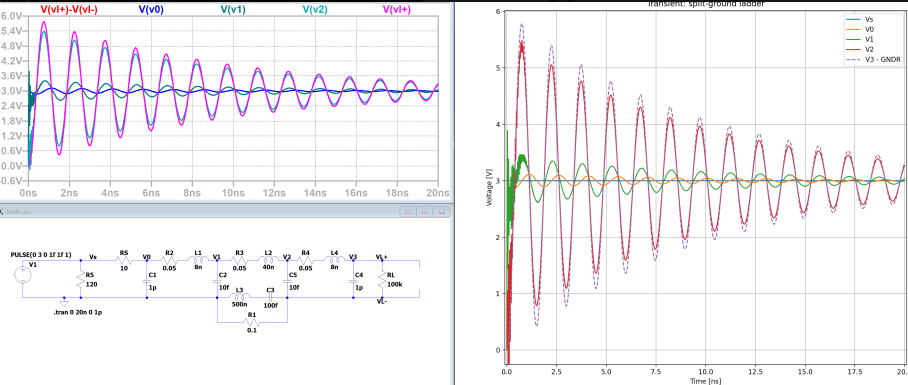
Ground Plane Split Example 1
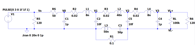
In this example, the source and load are matched but there is a split in a ground plane.
The representative circuit is shown below. The split in the ground plane is modeled by creating a separate, "local ground" on the right side of the circuit that as an inductor and capacitor branch and a parallel resistor connecting it to the true ground.
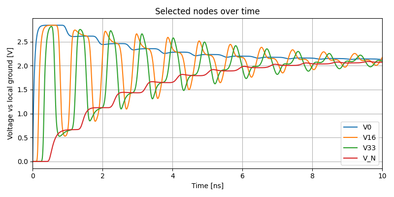
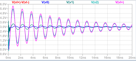
The LTspice results are shown below.
The LTspice results are compared to the Python simulation. results
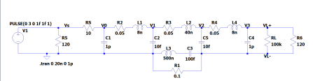
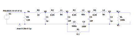
Ground Plane Split Example 2
In this example, the source and load are matched but there is a split in a ground plane. It varies with the prior example by changing key component values in the model, providing a completely different response.
Circuit
The results of the simulation are below.
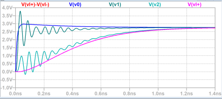
Ground Plane Split with Mismatched Load
This example includes both the ground plate split and a mismatched source and load impedance.
The circuit in LTspice is shown below
The LTspice simulation results are below
A comparison between the LTspice simulation and Python simulation are below