| images | ||
| modbus_tcp_client.cpp | ||
| modbus_tcp_client.h | ||
| README.md | ||
Purpose
The purpose of this library is to provide a lightweight, minimal import C++ structure for connecting to a MODBUS TCP client.
Specifically, this library was created for use in PX4 development using the PX4 toolkit in Simulink.
Usage
There are two ways to use the class. The first method is to construct the class with the server's IP address and port. Then, the class provides functions for reading/writing coils, discrete inputs, and registers. The second, preferred method, has the constructor allocate memory for the coils, discrete inputs, and registers that should exist for the entire session. A separate set of functions are exposed that has the class update all values at once, saving on network throughput and latency.
Types
The following enum class is used internally for the class to create the correct packet for MODBUS TCP communication.
enum class ModbusFunction : uint8_t {
    READ_COIL = 0x01,
    READ_DISCRETE_INPUT = 0x02,
    READ_HOLDING_REGISTER = 0x03,
    READ_INPUT_REGISTER = 0x04,
    WRITE_SINGLE_COIL = 0x05,
    WRITE_SINGLE_HOLDING_REGISTER = 0x06,
    WRITE_MULTIPLE_COILS = 0x0F,
    WRITE_MULTIPLE_HOLDING_REGISTERS = 0x10
};
The ModbusError enum class is used for returning errors that could have occurred during function calls.
enum class ModbusError {
    NONE = 0,
    TIMEOUT,
    INVALID_RESPONSE,
    CONNECTION_LOST,
    EXCEPTION_RESPONSE,
    INVALID_REQUEST
};
Method 1: Manual Control
The manual control method is best for when the client only needs to query a handful of coils/DI/registers at a time. For large server's, the automatic control method is preferred.
The manual control constructor requires only the server's IP and port.
ModbusTCPClient(const char* ip, int port);
The class then exposed the following functions for use. The first group provides read access to the server. The return types are all ModbusError and the data is stored in the final argument passed into the function call. This means the client must allocate a buffer before calling the read functions. For embedded devices, like STM32s, it is better to allocate the total expected size that the coils/DI/registers will take up and use the same buffer rather than allocating, freeing, re-allocating, ....
ModbusError readCoil(int address, bool &coilState);
ModbusError readMultipleCoils(int address, int count, bool coilStates[]);
ModbusError readDiscreteInput(int address, bool &discreteInput);
ModbusError readMultipleDiscreteInputs(int address, int count, bool discreteInputs[]);
ModbusError readHoldingRegister(int address, uint16_t &holdingRegister);
ModbusError readMultipleHoldingRegisters(int address, int count, uint16_t holdingRegisters[]);
ModbusError readInputRegister(int address, uint16_t &inputRegister);
ModbusError readMultipleInputRegisters(int address, int count, uint16_t inputRegisters[]);
The writing functions similarly return ModbusError and are straight-forward.
ModbusError writeCoil(int address, bool value);
ModbusError writeMultipleCoils(int address, int count, const bool values[]);
ModbusError writeHoldingRegister(int address, uint16_t value);
ModbusError writeMultipleHoldingRegisters(int address, int count, const uint16_t values[]);
Method 2: Automatic Control (Preferred for Larger Number of Coils/DI/Registers)
The automatic control method is preferred for clients that need to request large amounts of data at a time, usually at fixed time intervals. This method ensures the use of the "multiple" read and write functions rather than reading/writing to a single coil/DI/register at a time. Additionally, this class allocates the memory to store all of the server's data on the client. This removes the need for the client to manually allocate space before every read.
The automatic control constructor takes in the server IP and port, as well as the number of coils, discrete inputs (DI), input registers, holding registers, as well as the start offset for each.
ModbusTCPClient(const char* ip, int port, int numCoils, int numDI, int numIR, int numHR,
                int startCoils = 0, int startDI = 0, int startIR = 0, int startHR = 0);
The constructor initializes the following pointers for storing data from reads and for buffering the data before a write. These are all private and accessed through getters.
bool* coilsRead;       // Actual state from PLC
bool* coilsWrite;      // Desired state to write
bool* discreteInputs;  // Only read
uint16_t* inputRegisters;        // Only read
uint16_t* holdingRegistersRead;  // Actual values from PLC
uint16_t* holdingRegistersWrite; // Desired values to write
Reading
In order to read data from the server, all the user must do is call ModbusError readAll();. This will update all of the internal pointers to the data from the server. Then the getters can be used to retrieve the data for use elsewhere.
The following getters are used for retrieving the values from the internal buffers. For retrieving single values, the return type is the type requested. For requests of multiple data elements, the return type is ModbusError but is limited to either ModbusError::NONE or ModbusError::INVALID_REQUEST if the user requested data out of range based on the constructor.
bool getDiscreteInput(int address) const;
bool getCoil(int address) const;
bool getDesiredCoil(int address) const;
uint16_t getInputRegister(int address) const;
uint16_t getHoldingRegister(int address) const;
uint16_t getDesiredHoldingRegister(int address) const;

ModbusError getMultipleCoils(int startAddress, int count, bool* destination) const;
ModbusError getMultipleDiscreteInputs(int startAddress, int count, bool* destination) const;
ModbusError getMultipleInputRegisters(int startAddress, int count, uint16_t* destination) const;
ModbusError getMultipleHoldingRegisters(int startAddress, int count, uint16_t* destination) const;
Writing
In order to write data to the server, the user must first set the internal buffers to the correct data before writing. This is achieved through the following functions.
void setCoil(int address, bool value);
void setHoldingRegister(int address, uint16_t value);
TODO: Add setMultipleCoil and setMultipleHoldingRegisters
Then, the user can call ModbusError writeAll(); while will write the data from bool* coilsWrite; and uint16_t* holdingRegistersWrite; to the server.
Example Simulink Setup
Add the header and source files into the code generation setup of the Simulink model. Then, create custom C blocks for reading and writing. In the context of PX4, the uORB topics are created for each of the data types.
TODO: Add details on setting up uORB topics and Simulink code generation setup.
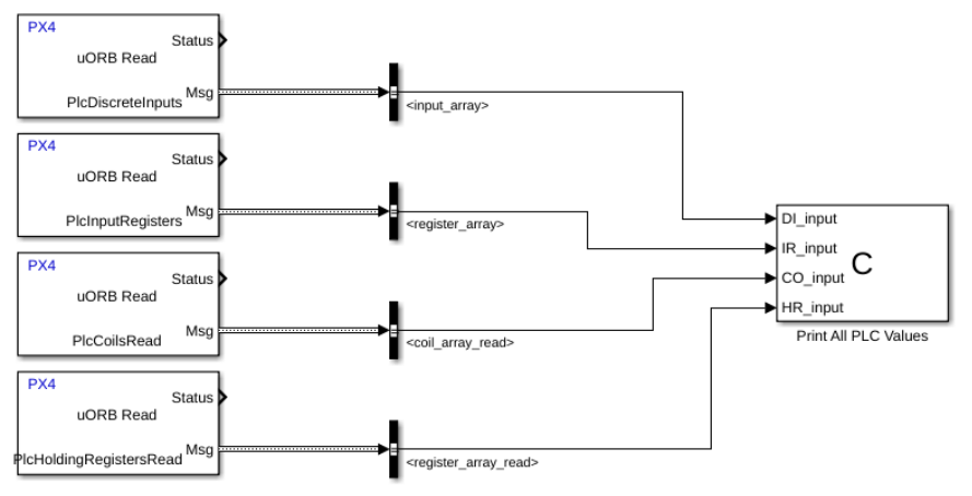
PX4 Reading Setup
The setup can easily be used to transfer the data from the coils, DI, and registers from the server into the client's (in this case a Pixhawk running PX4) uORB topic bus. This is very convenient as the uORB message bus is very well supported and provides incredible ease of use for data management and telemetry.
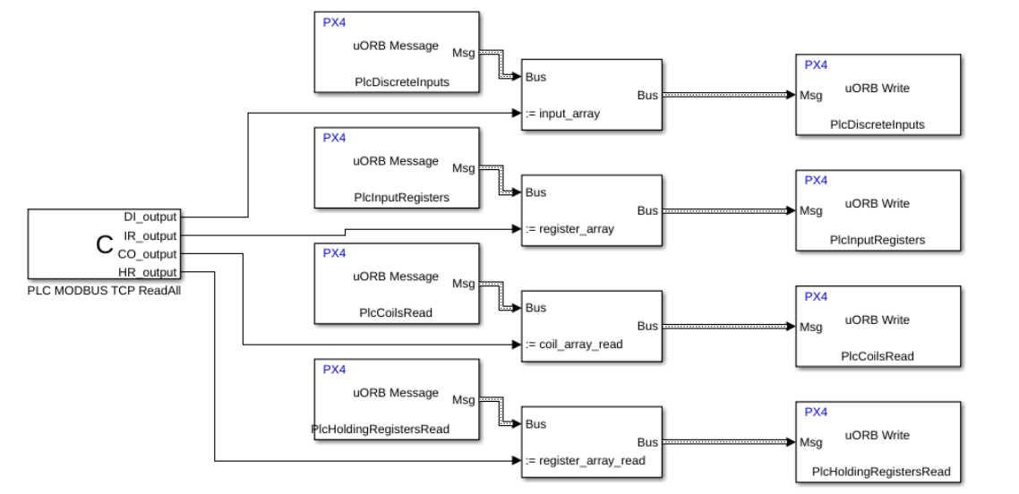
PX4 Writing Setup
Likewise, it is convenient to take the values stored in the uORB message bus and write them to the server.