3.8 KiB
Differential Amplifier for mV/V Instrumentation
Project Overview
This project focuses on developing a differential amplifier tailored for mV/V instrumentation, specifically designed for use with load cells and other precision sensors. The amplifier boosts the signal to a level appropriate for reading by standard analog-to-digital converters (ADCs), like those found in Arduino platforms, providing a significant gain while also adjusting the zero-level output voltage for optimal ADC utilization.
Key Features
- High Gain Capability: Achieves a gain factor of approximately 100, ideal for amplifying millivolt signals from precision sensors to usable levels.
- Output Offset Adjustment: Ensures that a 0 mV differential input translates to a 2.5V output, maximizing the dynamic range of ADCs that operate within a 0-5V range.
- Calibration with Analog Discovery 3: Leverages the capabilities of the Analog Discovery 3 to automate the calibration process, enhancing the accuracy and reliability of the amplifier.
Calibration Methodology
Calibration is conducted using the Analog Discovery 3, which acts as both a signal generator and data logger, ensuring precise control and measurement of input-output relationships. The calibration script must be loaded into the Digilent WaveForms software.
Steps Involved:
- Signal Generation: Differential voltages ranging from -20mV to +20mV are generated in increments (e.g., 0.5mV steps) to simulate sensor output.
- Data Logging: During each input step, the amplifier's output is sampled over a 1-second interval to obtain average values.
- Repeated Measurements: Multiple sweeps across the entire voltage range are conducted to ensure data consistency and reliability.
- Data Analysis: A linear regression analysis is applied to the logged data to determine the amplifier's gain and offset, along with their respective uncertainties.
Implementation Details
The calibration script automates the signal generation, data logging, and analysis process, providing a robust framework for ensuring the amplifier's accuracy. This script is located at src/analog_discovery_code.
- Customizable Parameters: Users can set the voltage range, step size, and the number of sweeps.
- Efficient Data Handling: The script logs both input and output values for each voltage step, ensuring thorough data collection.
- Advanced Analysis: Uses linear regression to compute key parameters (gain and offset), incorporating uncertainty analysis to gauge calibration precision.
Workflow Example:
- Initiate Calibration: Load the calibration script into the Digilent WaveForms software and run it to start the process.
- Configure Parameters: Define the input sweep range, step size, and loop count.
- Data Acquisition: Log input and output voltages, averaging over defined intervals.
- Compute Results: The Python script
src/analyze_data.pyanalyzes the data, calculates gain and offset, and reports results with uncertainties.
Visual Documentation
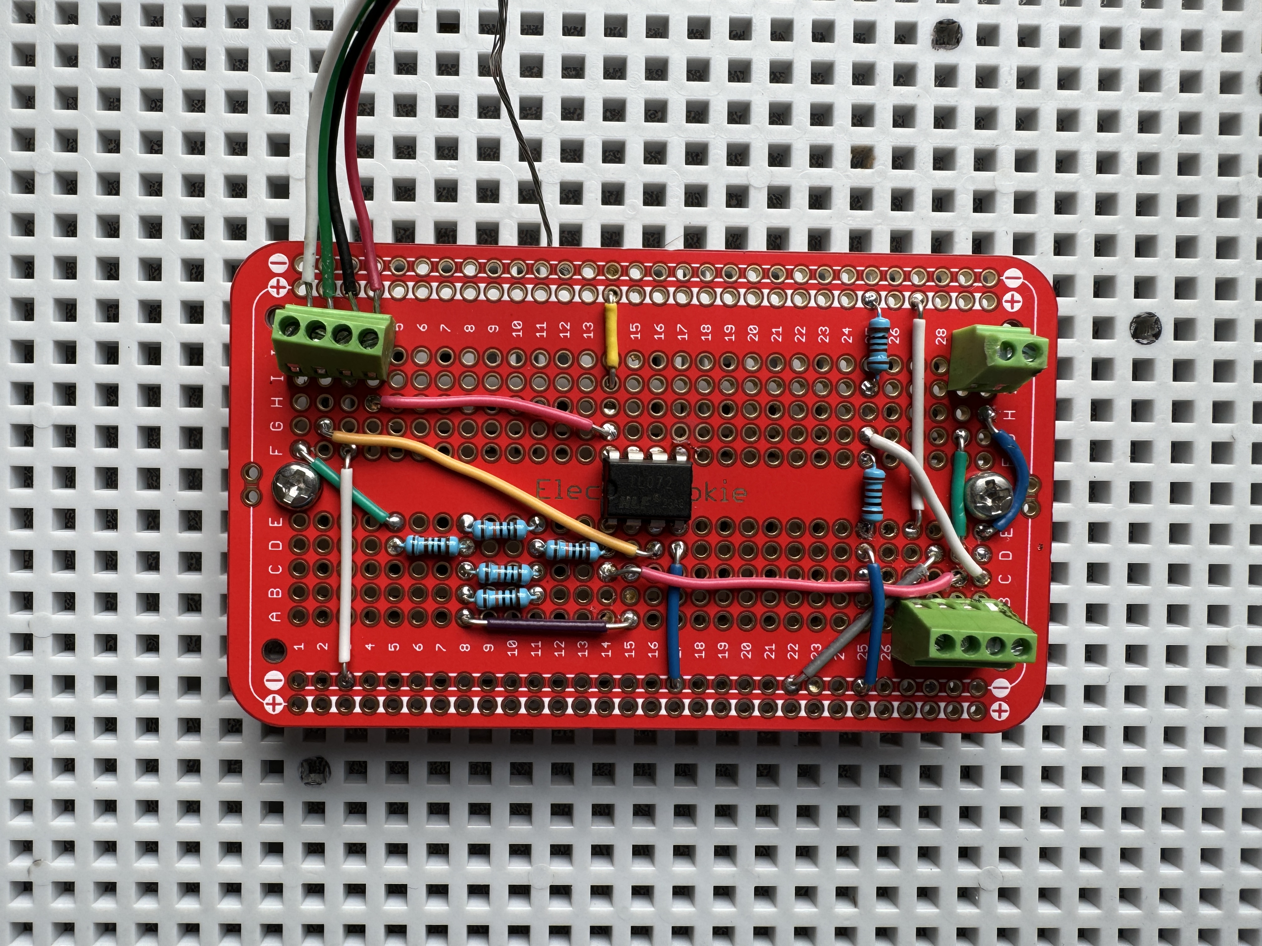
Below are visual representations of the amplifier's performance, illustrating the calibration results and the physical setup.
Calibration Outputs
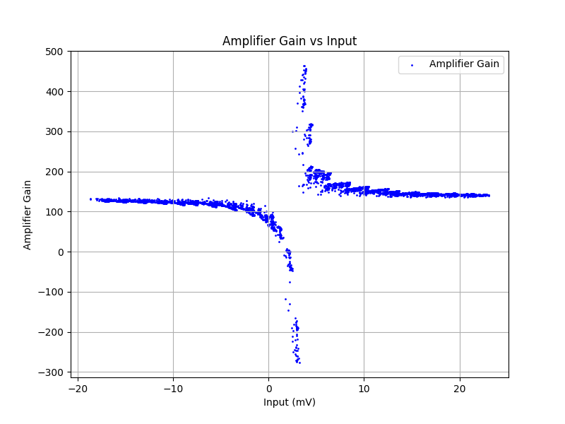
-
Amplifier Gain vs Input: Displays the relationship between input voltage and amplifier gain.
-
Amplifier Output vs Input: Shows how the output voltage varies with input signal.

This comprehensive documentation and systematic approach ensure that the differential amplifier is well-suited for high-precision applications, offering reliable performance tailored for mV/V instrumentation.