# Differential Amplifier for mV/V Instrumentation
## Project Overview
This project focuses on developing a differential amplifier tailored for mV/V instrumentation, specifically designed for use with load cells and other precision sensors. The amplifier boosts the signal to a level appropriate for reading by standard analog-to-digital converters (ADCs), like those found in Arduino platforms, providing a significant gain while also adjusting the zero-level output voltage for optimal ADC utilization.
## Key Features
- **High Gain Capability**: Achieves a gain factor of approximately 100, ideal for amplifying millivolt signals from precision sensors to usable levels.
- **Output Offset Adjustment**: Ensures that a 0 mV differential input translates to a 2.5V output, maximizing the dynamic range of ADCs that operate within a 0-5V range.
- **Calibration with Analog Discovery 3**: Leverages the capabilities of the Analog Discovery 3 to automate the calibration process, enhancing the accuracy and reliability of the amplifier.
## Calibration Methodology
Calibration is conducted using the Analog Discovery 3, which acts as both a signal generator and data logger, ensuring precise control and measurement of input-output relationships. The calibration script must be loaded into the Digilent WaveForms software.
### Steps Involved:
1. **Signal Generation**: Differential voltages ranging from -20mV to +20mV are generated in increments (e.g., 0.5mV steps) to simulate sensor output.
2. **Data Logging**: During each input step, the amplifier's output is sampled over a 1-second interval to obtain average values.
3. **Repeated Measurements**: Multiple sweeps across the entire voltage range are conducted to ensure data consistency and reliability.
4. **Data Analysis**: A linear regression analysis is applied to the logged data to determine the amplifier's gain and offset, along with their respective uncertainties.
## Implementation Details
The calibration script automates the signal generation, data logging, and analysis process, providing a robust framework for ensuring the amplifier's accuracy. This script is located at `src/analog_discovery_code`.
- **Customizable Parameters**: Users can set the voltage range, step size, and the number of sweeps.
- **Efficient Data Handling**: The script logs both input and output values for each voltage step, ensuring thorough data collection.
- **Advanced Analysis**: Uses linear regression to compute key parameters (gain and offset), incorporating uncertainty analysis to gauge calibration precision.
### Workflow Example:
1. **Initiate Calibration**: Load the calibration script into the Digilent WaveForms software and run it to start the process.
2. **Configure Parameters**: Define the input sweep range, step size, and loop count.
3. **Data Acquisition**: Log input and output voltages, averaging over defined intervals.
4. **Compute Results**: The Python script `src/analyze_data.py` analyzes the data, calculates gain and offset, and reports results with uncertainties.
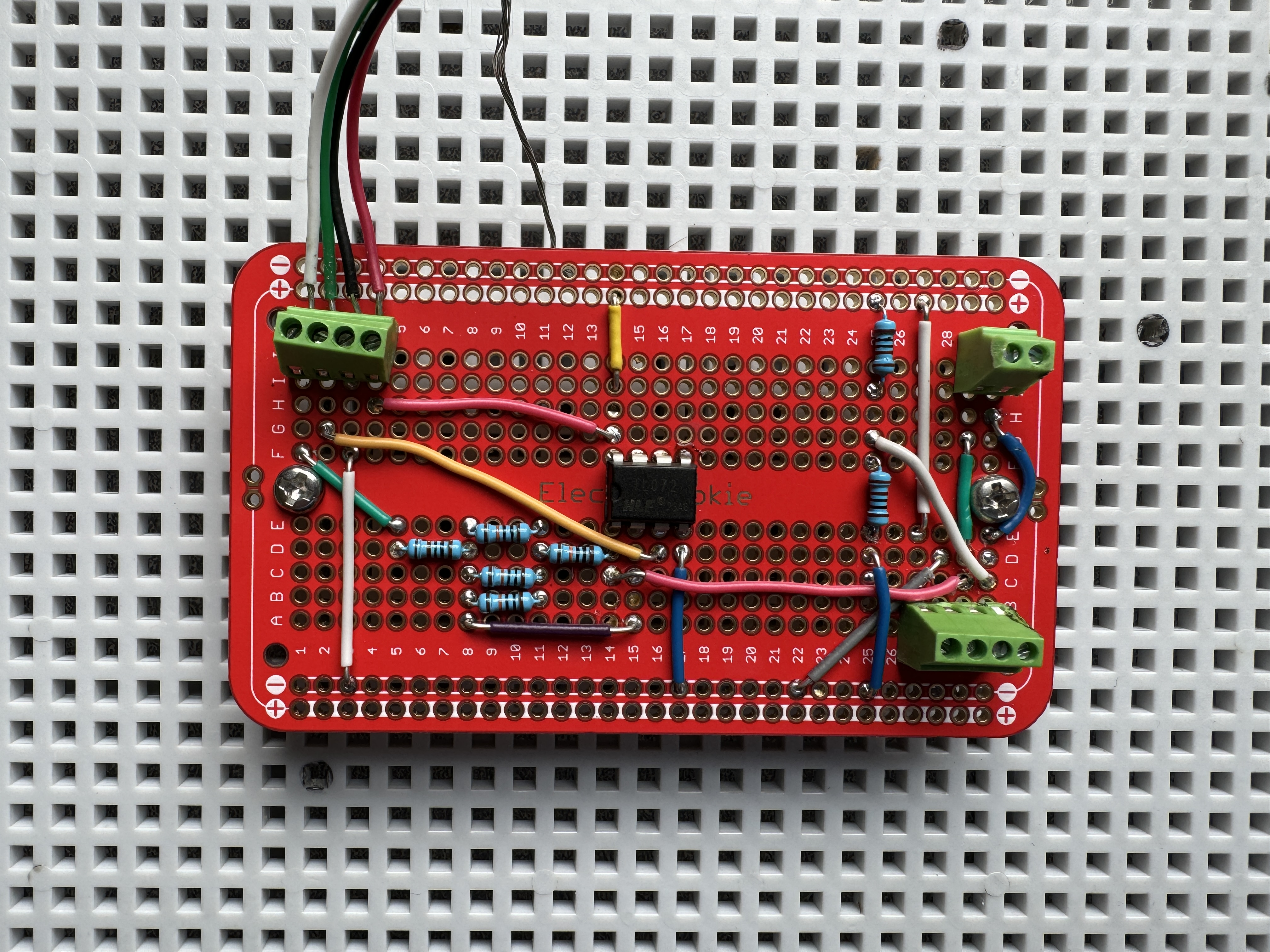
## Visual Documentation
Below are visual representations of the amplifier's performance, illustrating the calibration results and the physical setup:
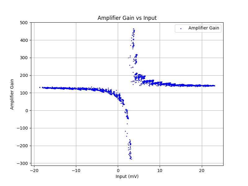
 ### Calibration Outputs
- **Amplifier Gain vs Input**: Displays the relationship between input voltage and amplifier gain.
### Calibration Outputs
- **Amplifier Gain vs Input**: Displays the relationship between input voltage and amplifier gain.
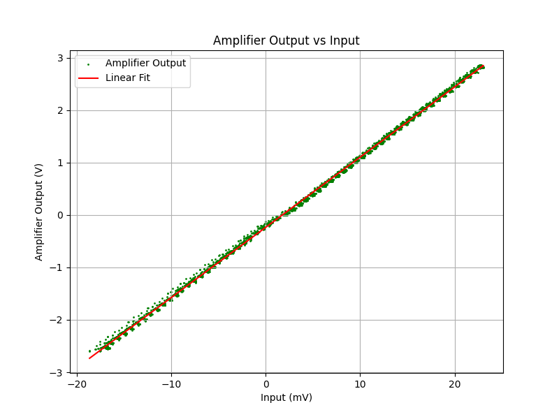
 - **Amplifier Output vs Input**: Shows how the output voltage varies with input signal.
 This comprehensive documentation and systematic approach ensure that the differential amplifier is well-suited for high-precision applications, offering reliable performance tailored for mV/V instrumentation.